FUEL PRESSURE PULSATION DAMPER (for Direct Injection) INSTALLATION

-
PRECAUTION
CAUTION:
-
Do not smoke or work near an open flame when handling the fuel system.
-
Keep gasoline away from rubber or leather parts.
-
Do not allow fuel to spray when removing the pipe between the high pressure side fuel pump and the fuel injector. The fuel in the pipe is highly pressurized.
-
-
INSTALL FUEL PRESSURE PULSATION DAMPER ASSEMBLY (for Direct Injection)
-
Apply a light coat of engine oil to the threads and gasket seating surfaces of the 2 fuel pressure pulsation damper assemblies.
-
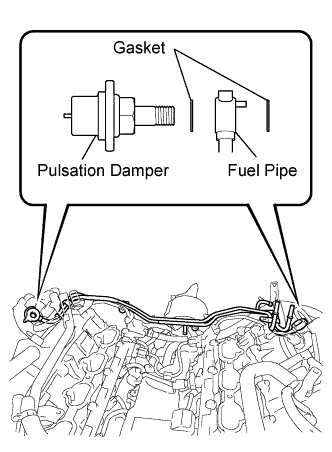
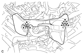
Temporarily install the 2 fuel pressure pulsation damper assemblies together with 4 new gaskets and the No. 1 fuel pipe sub-assembly.
-
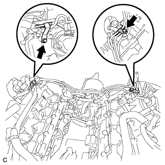
Install the 2 clamp bolts.
- Torque:
- 10 N*m { 102 kgf*cm, 7 ft.*lbf }
-
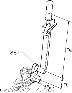
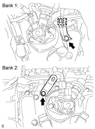
Text in Illustration *a Fulcrum Length: 300 mm *b Fulcrum Length: 52 mm Using SST, tighten the 2 fuel pressure pulsation damper assemblies.
- SST
- 09612-24014 ( 09617-24011 )
- Torque:
- without SST
- 36 N*m { 367 kgf*cm, 27 ft.*lbf }
- with SST
- 31 N*m { 313 kgf*cm, 23 ft.*lbf }
Tech Tips
-
The "with SST" torque value is effective when using SST with a fulcrum length of 52 mm (2.05 in.) and a torque wrench with a fulcrum length of 300 mm (11.8 in.).
-
The "with SST" torque value is effective when SST is parallel to the torque wrench.
-
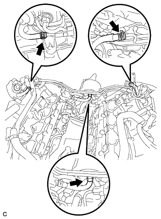
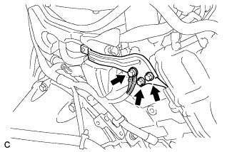
Connect the 3 fuel hoses.
-
Install the 2 brackets with the 2 bolts and then connect the harness clamp.
- Torque:
- 10 N*m { 102 kgf*cm, 7 ft.*lbf }
-
-
INSTALL NO. 3 COVER SUB-ASSEMBLY
-
Install the No. 3 cover sub-assembly with the 2 clips.
-
Install the bracket and wire harness with the 3 bolts.
- Torque:
- 10 N*m { 102 kgf*cm, 7 ft.*lbf }
-
-
INSTALL ENGINE WIRE
-
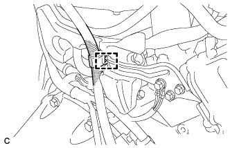
Connect the harness clamp then install the engine wire.
-
-
CONNECT NO. 1 FUEL HOSE
-

Push in the fuel tube connector to the No. 1 fuel hose until the fuel tube connector makes a "click" sound.
Note
-
Check that there is no damage or foreign objects on the fuel pipe connectors.
-
After connecting, check that the fuel tube connector and the pipe are securely connected by pulling on them.
-
-
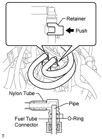
Push in the fuel tube connector to the No. 1 fuel hose until the fuel tube connector makes a "click" sound.
-
Push down on the retainer to lock it in place.
Note
-
Check that there is no damage or foreign objects on the fuel pipe connectors.
-
After connecting, check that the fuel tube connector and the pipe are securely connected by pulling on them.
-
-
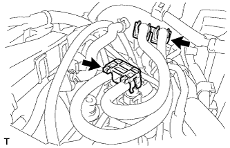
Install the 2 fuel pipe clamps.
-
-
INSTALL INTAKE AIR SURGE TANK ASSEMBLY
-
Install the intake air surge tank assembly Click here.
-
-
CONNECT CABLE TO NEGATIVE BATTERY TERMINAL
Note
When disconnecting the cable, some systems need to be initialized after the cable is reconnected Click here.
-
INSPECT FOR FUEL LEAK
-
Check fuel pump operation.
-
Connect the intelligent tester to the DLC3.
-
Turn the engine switch on (IG).
Note
Do not start the engine.
-
Turn the intelligent tester on.
-
Enter the following menus: Powertrain / Engine / Active Test / Control the Fuel Pump / Speed.
-
Check for pressure in the fuel inlet tube from the fuel line. Check that sounds of fuel flowing in the fuel tank can be heard. If no sounds can be heard, check the instrument panel junction block, fuel pump, ECM and wiring connectors.
-
-
Inspect for fuel leaks.
-
Check that there are no fuel leaks from the fuel system after performing any maintenance. If there is a fuel leak, repair or replace parts as necessary.
-
-
Turn the engine switch off.
-
Disconnect the intelligent tester from the DLC3.
-