FUEL PUMP (for High Pressure) INSTALLATION

-
INSTALL FUEL PUMP ASSEMBLY (for Bank 1)
-
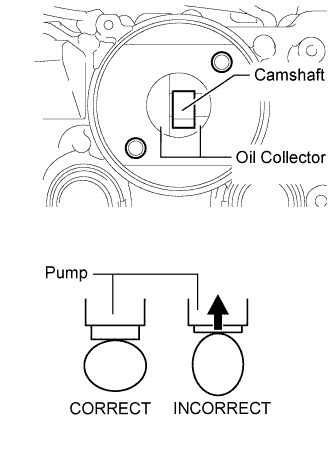
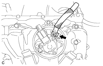
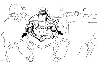
Rotate the crankshaft until the base circle of the fuel pump cam is facing the hole in the cylinder head cover as shown in the illustration.
Tech Tips
Setting the cam in this position does not compress the fuel pump plunger, making it easier to install the fuel pump assembly and No. 3 fuel pipe sub-assembly later.
-
Pour 30 cm3(1.8 cu in.) of engine oil through the hole in the cylinder head cover into the cylinder head oil collector.
-
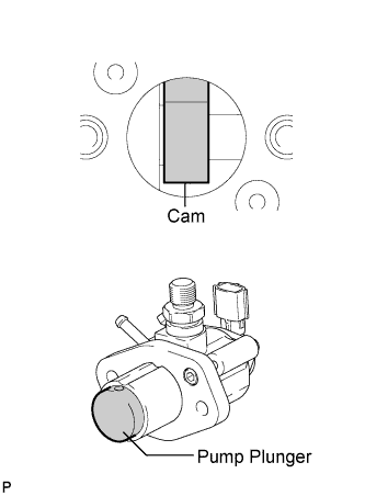
Apply a coat of engine oil to the fuel pump activation cam and pump plunger.
-
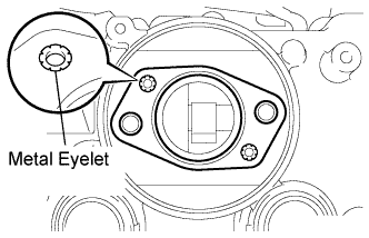
Install a new fuel pump insulator to the cylinder head cover. Then pass the 2 stud bolts through the holes of the fuel pump assembly and set them on the fuel pump insulator.
Note
Install the fuel pump insulator so that the open sides of the metal eyelets are facing outward as shown in the illustration.
-
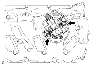
Temporarily install the 2 nuts and fuel pump assembly.
-
Connect the fuel hose.
-
-
INSTALL NO. 3 FUEL PIPE SUB-ASSEMBLY
-
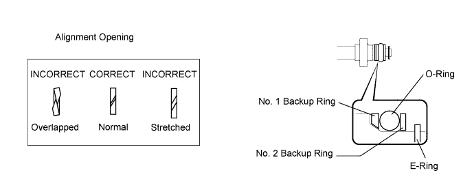
Install a new O-ring, new backup rings (No. 1 and No. 2) and a new E-ring to the No. 3 fuel pipe sub-assembly as shown in the illustration.
Note
-
Check that there is no foreign matter or damaged areas in the No. 3 fuel pipe sub-assembly O-ring groove.
-
Check that the No. 1 and No. 2 backup rings are installed in the correct direction.
-
Make sure that the backup rings and O-ring are installed in the correct order.
-
Check that the alignment openings of the backup rings are not overlapped or stretched as shown in the illustration.
-
After installing the O-ring, check that it is not contaminated with foreign matter or damaged.
-
-
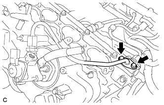
Temporarily install the No. 3 fuel pipe sub-assembly to the delivery pipe with the 2 bolts.
-
Temporarily install the No. 3 fuel pipe sub-assembly to the fuel pump assembly.
Note
Be careful not to damage the sealing surface of the fuel pipe when temporarily installing the No. 3 fuel pipe sub-assembly.
-
Install the No. 3 fuel pipe sub-assembly to the delivery pipe with the 2 bolts and tighten them in several passes.
- Torque:
- 10 N*m { 102 kgf*cm, 7 ft.*lbf }
-
Install the fuel pump assembly with the 2 nuts and tighten them in several passes.
- Torque:
- 25 N*m { 255 kgf*cm, 18 ft.*lbf }
-
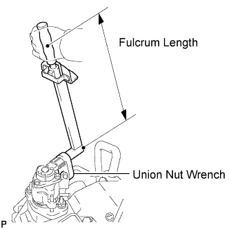
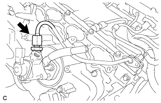
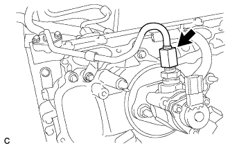
Using a 19 mm union nut wrench, tighten the union nut.
- Torque:
- without a union nut wrench
- 30 N*m { 306 kgf*cm, 22 ft.*lbf }
- with a union nut wrench
- 27 N*m { 275 kgf*cm, 20 ft.*lbf }
Note
There must be absolutely no free play in the union on the fuel pump assembly side. If the union on the fuel pump assembly side has free play, replace the fuel pump assembly.
Tech Tips
-
Use a torque wrench with a fulcrum length of 30 cm (11.8 in.).
-
Make sure that the union nut wrench and torque wrench are connected in a straight line.
-
Connect the connector to the fuel pump assembly.
-
-
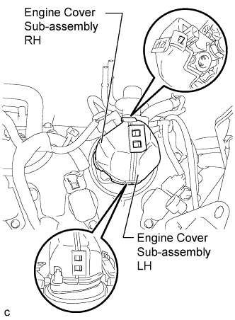
INSTALL ENGINE COVER SUB-ASSEMBLY (for Bank 1)
-
Attach the 5 claws and install the engine covers LH and RH to the fuel pump assembly.
-
-
INSTALL FUEL PUMP ASSEMBLY (for Bank 2)
Tech Tips
Use the same procedure as for the bank 1 side.
-
INSTALL NO. 2 FUEL PIPE SUB-ASSEMBLY
-
Install a new O-ring, new backup rings (No. 1 and No. 2) and a new E-ring to the No. 2 fuel pipe subassembly as shown in the illustration.
Note
-
Check that there is no foreign matter or damaged areas in the No. 2 fuel pipe sub-assembly O-ring groove.
-
Check that the No. 1 and No. 2 backup rings are installed in the correct direction.
-
Make sure that the backup rings and O-ring are installed in the correct order.
-
Check that the alignment openings of the backup rings are not overlapped or stretched as shown in the illustration.
-
After installing the O-ring, check that it is not contaminated with foreign matter or damaged.
-
-
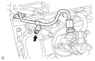
Temporarily install the No. 2 fuel pipe to the cylinder head cover with the bolt.
-
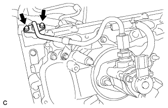
Temporarily install the No. 2 fuel pipe sub-assembly to the delivery pipe with the 2 bolts.
-
Temporarily install the No. 2 fuel pipe sub-assembly to the fuel pump assembly.
Note
Be careful not to damage the sealing surface of the fuel pipe when temporarily installing the No. 2 fuel pipe sub-assembly.
-
Install the No. 2 fuel pipe to the delivery pipe with the 2 bolts and tighten them in several passes.
- Torque:
- 10 N*m { 102 kgf*cm, 7 ft.*lbf }
-
Install the fuel pump assembly with the 2 nuts and tighten them in several passes.
- Torque:
- 25 N*m { 255 kgf*cm, 18 ft.*lbf }
-
Using a 19 mm union nut wrench, tighten the union nut.
- Torque:
- without a union nut wrench
- 30 N*m { 306 kgf*cm, 22 ft.*lbf }
- with a union nut wrench
- 27 N*m { 275 kgf*cm, 20 ft.*lbf }
Note
There must be absolutely no free play in the union on the fuel pump assembly side. If the union on the fuel pump assembly side has free play, replace the fuel pump assembly.
Tech Tips
-
Use a torque wrench with a fulcrum length of 30 cm (11.8 in.).
-
Make sure that the union nut wrench and torque wrench are connected in a straight line.
-
Install the No. 2 fuel pipe sub-assembly to the cylinder head cover with the bolt.
- Torque:
- 10 N*m { 102 kgf*cm, 7 ft.*lbf }
-
Connect the connector to the fuel pump assembly.
-
-
INSTALL ENGINE COVER SUB-ASSEMBLY (for Bank 2)
Tech Tips
Use the same procedure as for the bank 1 side.
-
INSTALL FUEL PRESSURE PULSATION DAMPER ASSEMBLY (for Direct Injection)
-
Install the fuel pressure pulsation damper assembly and No. 1 fuel pipe sub-assembly Click here.
-
-
CONNECT CABLE TO NEGATIVE BATTERY TERMINAL
Note
When disconnecting the cable, some systems need to be initialized after the cable is reconnected Click here.
-
INSPECT FOR FUEL LEAK
-
Check fuel pump operation.
-
Connect the intelligent tester to the DLC3.
-
Turn the engine switch on (IG).
Note
Do not start the engine.
-
Turn the intelligent tester on.
-
Enter the following menus: Powertrain / Engine / Active Test / Control the Fuel Pump / Speed.
-
Check for pressure in the fuel inlet tube from the fuel line. Check that sounds of fuel flowing in the fuel tank can be heard. If no sounds can be heard, check the instrument panel junction block, fuel pump, ECM and wiring connectors.
-
-
Inspect for fuel leaks.
-
Check that there are no fuel leaks from the fuel system after performing any maintenance. If there is a fuel leak, repair or replace parts as necessary.
-
-
Turn the engine switch off.
-
Disconnect the intelligent tester from the DLC3.
-