FUEL PRESSURE REGULATOR INSTALLATION

-
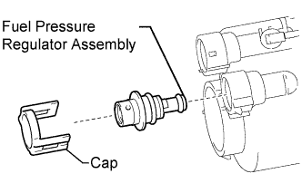
INSTALL FUEL PRESSURE REGULATOR ASSEMBLY
-
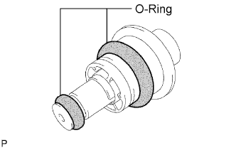
Apply a light coat of gasoline to 2 new O-rings, and install them onto the fuel pressure regulator assembly.
-
Install the fuel pressure regulator assembly to the fuel filter.
-
Attach the 2 claws of the fuel filter and install the cap.
Note
-
Make sure that the fuel main valve and fuel pressure regulator assembly are not installed backward. If installed backward, the engine may stall.
-
Make sure that the O-rings are not cut or pinched during installation.
-
Attach the claws securely.
-
-
-
INSTALL FUEL MAIN VALVE ASSEMBLY
-
Apply a light coat of gasoline to 2 new O-rings, and install them onto the fuel main valve assembly.
-
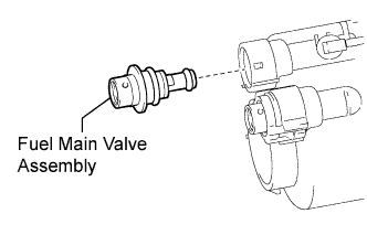
Install the fuel main valve assembly to the fuel filter.
Note
-
Make sure that the fuel main valve assembly and fuel pressure regulator assembly are not installed backward. If installed backward, the engine may stall.
-
Make sure that the O-rings are not cut or pinched during installation.
-
-
-
INSTALL FUEL PUMP ASSEMBLY
-
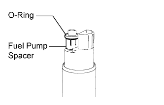
Apply gasoline to a new O-ring. Then install the O-ring and fuel pump spacer to the fuel pump assembly.
-
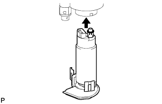
Engage the 5 claws on the fuel filter and install the fuel pump assembly to the pump filter.
Note
-
Make sure that the O-ring is not cut or pinched during the installation.
-
Attach the claws securely.
-
-
-
INSTALL NO. 1 FUEL SUCTION SUPPORT
-
Install the No. 1 fuel suction support to the fuel filter.
-
-
INSTALL FUEL PUMP HARNESS
-
Connect the fuel pump connector to the fuel pump assembly.
-
-
TEMPORARILY INSTALL JET PUMP
-
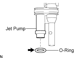
Apply gasoline to a new O-ring and install it to the jet pump.
-
Temporarily install the jet pump to the No. 1 fuel sub-tank.
-
-
INSTALL FUEL FILTER
-
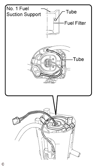
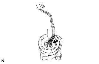
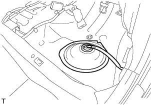
Temporarily install fuel filter.
Note
When temporarily installing the fuel filter, pass the tube under the protrusion at the top of the fuel filter as shown in the illustration.
-
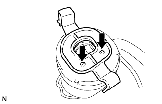
Install the fuel filter to the No. 1 fuel sub-tank and attach the 2 claws.
-
Install the jet pump to the No. 1 fuel sub-tank as shown in the illustration.
-
-
INSTALL FUEL SUCTION PLATE SUB-ASSEMBLY
-
Install the 2 spring to the fuel suction plate sub-assembly shaft.
-
Install the fuel suction plate sub-assembly to the No. 1 fuel sub-tank.
-
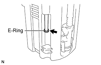
Install a new E-ring.
-
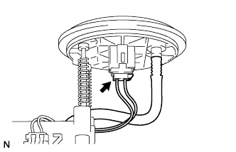
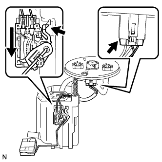
Connect the fuel pump connector to the fuel suction plate sub-assembly.
-
-
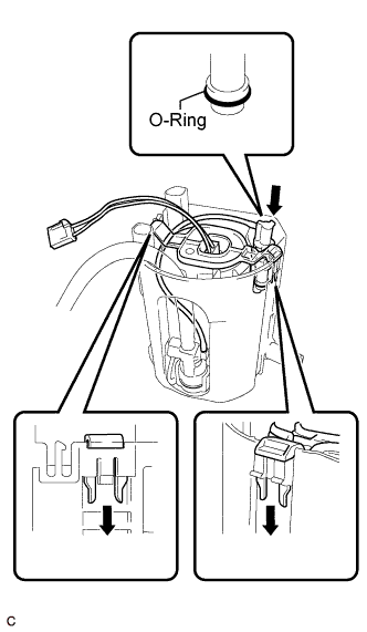
INSTALL FUEL SENDER GAUGE ASSEMBLY
-
Set the fuel sender gauge assembly to the No. 1 fuel sub-tank. Then slide the sender gauge assembly downward to install it.
-
Connect the fuel sender gauge assembly connector to the fuel suction plate sub-assembly.
Note
Do not touch the sender resistance plate or contact area.
-
-
INSTALL FUEL SUCTION WITH PUMP AND GAUGE TUBE ASSEMBLY
-
Install a new fuel suction tube set gasket onto the fuel tank.
-
Connect the fuel tube with the clip.
-
Set the fuel suction with pump and tube assembly to the fuel tank.
Note
-
Make sure that the fuel sender gauge assembly arm does not bend.
-
Do not damage the fuel tube.
-
-

Align the protrusion of the fuel suction with pump and gauge tube assembly and the cutout of the fuel tank vent tube set plate.
-
While holding the fuel suction with pump and gauge tube assembly by hand, install the fuel tank vent tube to the fuel tank with the 8 bolts.
- Torque:
- 6.0 N*m { 61 kgf*cm, 53 in.*lbf }
-
Connect the fuel pump tubes.
-
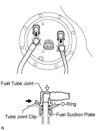
Push the fuel tube joint in the plug of the fuel suction plate, and then install the fuel tank main tube and fuel tank return vent tube with the 2 tube joint clips.
Note
-
Check that there are no scratches or foreign objects on the connecting parts.
-
Check that the fuel tube joint is inserted securely.
-
Check that the tube joint clips are on the collars of the fuel tube joints.
-
After installing the tube joint clips, check that the fuel tube joints have not been pulled off.
-
Be careful not to damage any clips. If a clip is damaged, replace it.
-
-
-
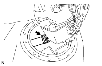
Connect the fuel suction tube connector.
-
-
CONNECT CABLE TO NEGATIVE BATTERY TERMINAL
Note
When disconnecting the cable, some systems need to be initialized after the cable is reconnected Click here.
-
INSPECT FOR FUEL LEAK
-
Check fuel pump operation.
-
Connect the intelligent tester to the DLC3.
-
Turn the engine switch on (IG).
Note
Do not start the engine.
-
Turn the intelligent tester on.
-
Enter the following menus: Powertrain / Engine / Active Test / Control the Fuel Pump / Speed.
-
Check for pressure in the fuel inlet tube from the fuel line. Check that sounds of fuel flowing in the fuel tank can be heard. If no sounds can be heard, check the instrument panel junction block, fuel pump, ECM and wiring connectors.
-
-
Inspect for fuel leaks.
-
Check that there are no fuel leaks from the fuel system after performing any maintenance. If there is a fuel leak, repair or replace parts as necessary.
-
-
Turn the engine switch off.
-
Disconnect the intelligent tester from the DLC3.
-
-
INSTALL NO. 2 REAR FLOOR SERVICE HOLE COVER
-
Install the No. 2 rear floor service hole cover with new butyl tape.
-
-
INSTALL NO. 3 ROOM PARTITION PAD
-
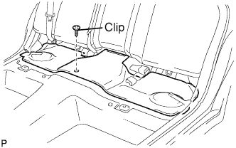
Install the No. 3 room partition pad with the clip.
-
-
INSTALL REAR SEAT CUSHION ASSEMBLY
-
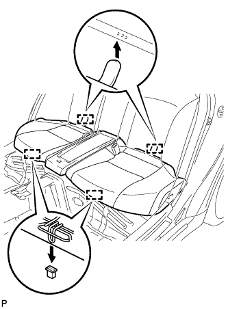
Engage the 2 rear hooks of the seat cushion to the child restraint seat anchor bracket.
-
Engage the 2 front hooks of the seat cushion to the vehicle body.
-
Confirm that the seat cushion is firmly installed.
Note
When installing the seat cushion, make sure the seat belt buckle is not under the seat cushion.
-