FUEL PRESSURE REGULATOR REMOVAL

-
DISCHARGE FUEL SYSTEM PRESSURE
-
Discharge fuel system pressure Click here.
-
-
DISCONNECT CABLE FROM NEGATIVE BATTERY TERMINAL
Note
When disconnecting the cable, some systems need to be initialized after the cable is reconnected Click here.
-
REMOVE REAR SEAT CUSHION ASSEMBLY
-
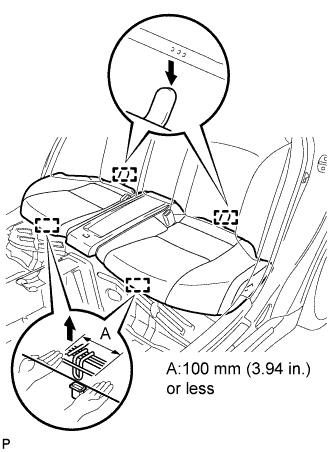
Disengage the 2 front hooks of the rear seat cushion assembly from the vehicle body.
Note
Follow the instructions below carefully as the cushion frame deforms easily.
-
Choose a hook to detach first. Place your hands near the hook as shown in the illustration. Then lift the seat cushion to detach the hook.
-
Repeat for the other hook.
-
-
Disengage the 2 rear hooks of the seat cushion from the child restraint seat anchor bracket.
-
Remove the rear seat cushion assembly.
-
-
REMOVE NO. 3 ROOM PARTITION PAD
-
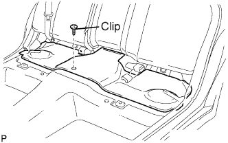
Remove the clip and No.3 room partition pad.
-
-
REMOVE NO. 2 REAR FLOOR SERVICE HOLE COVER
-
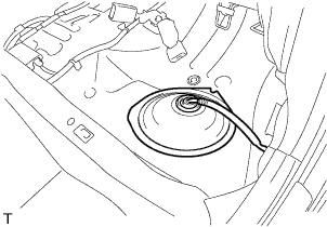
Remove the No. 2 rear floor service hole cover and disconnect the fuel suction tube connector.
-
-
REMOVE FUEL SUCTION WITH PUMP AND GAUGE TUBE ASSEMBLY
-
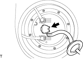
Disconnect the connector from the fuel suction with pump and gauge tube assembly.
-
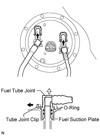
Disconnect fuel pump tubes.
Note
Before beginning this procedure, check for foreign matter on the joint clips. Clean if necessary.
-
Remove the 2 tube joint clips, fuel tank main tube and fuel tank return vent tube.
Note
-
Keep the O-rings free of foreign matter, as it becomes contaminated easily.
-
Do not use any tools in this procedure.
-
Do not forcefully bend or twist the tube.
-
Put the tube in a plastic bag to prevent damage and contamination.
-
If the fuel suction plate and tube are stuck together, pinch the tube and turn it carefully to disconnect it.
-
Be careful not to damage any clips. If a clip is damaged, replace it.
-
-
-
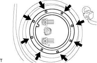
Remove the 8 bolts and the fuel tank vent tube set plate.
Tech Tips
While holding the fuel suction tube by hand, remove the fuel tank vent tube set plate.
-
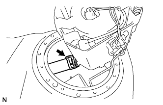
Disconnect the clip and fuel tube.
-
Remove the fuel suction with pump and gauge tube assembly and fuel suction tube set gasket from the fuel tank.
Note
-
Make sure that the fuel sender gauge assembly arm does not bend.
-
Do not damage the fuel tube.
-
-
-
REMOVE FUEL SENDER GAUGE ASSEMBLY
-
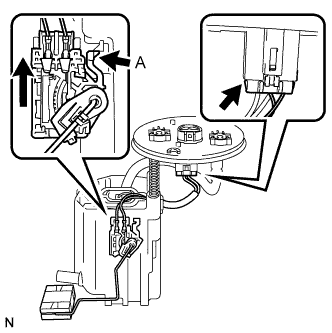
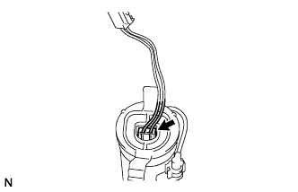
Disconnect the fuel sender gauge assembly connector from the fuel suction plate.
-
Press down on the fuel sender gauge assembly claw labeled A. Then slide the fuel sender gauge assembly upward.
Note
Do not touch the sender resistance plate or contact area.
-
-
SEPARATE FUEL SUCTION PLATE SUB-ASSEMBLY
-
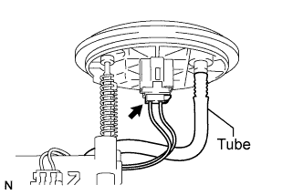
Disconnect the fuel pump connector from the fuel suction plate sub-assembly.
Note
-
Do not damage the wire harness.
-
Do not separate the tube indicated in the illustration Click here.
-
-
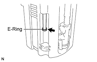
Using needle nose pliers, remove the E-ring.
-
Separate the fuel suction plate sub-assembly and remove the 2 spring from the No. 1 fuel sub-tank.
-
-
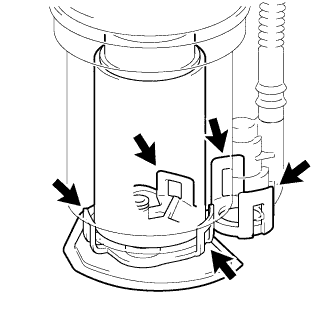
REMOVE FUEL FILTER
-
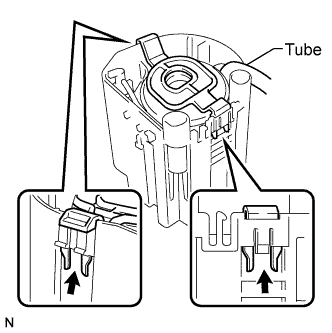
Disengage the 2 claws and remove the fuel filter from the No. 1 fuel sub-tank.
Note
Do not separate the tube indicated in the illustration Click here.
-
-
REMOVE JET PUMP
-
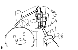
Using a screwdriver with the tip taped, remove the jet pump from the No. 1 fuel sub-tank.
-
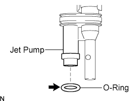
Remove the O-ring from the jet pump.
-
-
REMOVE FUEL PUMP HARNESS
-
Disconnect the fuel pump connector from the fuel pump assembly and then remove the fuel pump harness.
-
-
REMOVE NO. 1 FUEL SUCTION SUPPORT
-
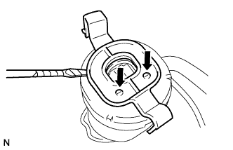
Using a screwdriver with the tip taped, disengage the 2 claw and remove the No. 1 fuel suction support.
-
-
REMOVE FUEL PUMP ASSEMBLY
-
Disengage the 5 claws on the fuel filter and remove the fuel pump assembly from the fuel filter.
-
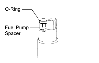
Remove the O-ring and fuel pump spacer from the fuel pump assembly.
-
-
REMOVE FUEL MAIN VALVE ASSEMBLY
-
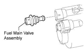
Remove the fuel main valve assembly from the fuel filter.
-
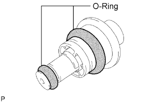
Remove the 2 O-rings from the fuel main valve assembly.
-
-
REMOVE FUEL PRESSURE REGULATOR ASSEMBLY
-
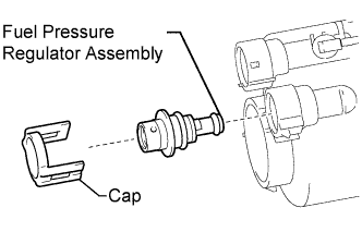
Detach the 2 claws of the fuel filter and remove the cap.
-
Remove the fuel pressure regulator assembly from the fuel filter.
-
Remove the 2 O-rings from the pressure regulator assembly.
-