FUEL INJECTOR (for Direct Injection) INSTALLATION

-
INSTALL FUEL DELIVERY PIPE PLUG
-
Apply engine oil to the threaded portion of the fuel delivery pipe.
Note
Make sure there is no gasoline on the threaded part of the fuel delivery pipe plug and fuel delivery pipe.
-
Install 2 new gaskets and the 2 fuel delivery pipe plugs to the fuel delivery pipe and No. 2 fuel delivery pipe.
- Torque:
- 33 N*m { 337 kgf*cm, 24 ft.*lbf }
-
-
INSTALL FUEL PIPE SUPPORT SUB-ASSEMBLY
-
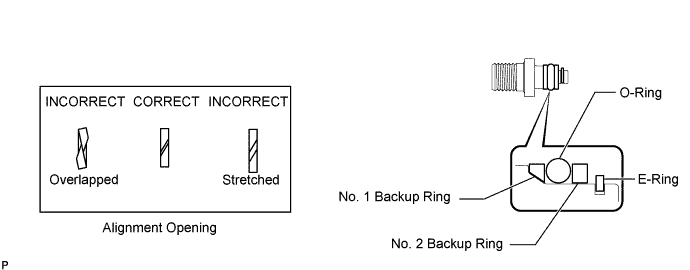
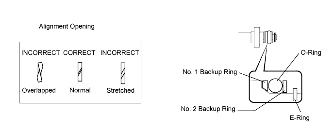
Install 2 new O-rings, 2 new No. 1 backup rings, 2 new No. 2 backup rings and 2 new E-rings to the 2 fuel pipe support sub-assemblies as shown in the illustration.
Note
-
Check that there is no foreign matter or damaged areas in the fuel pipe support sub-assembly O-ring groove.
-
Check that the No. 1 backup ring is installed in the correct direction.
-
Make sure that the backup rings and O-ring are installed in the correct order.
-
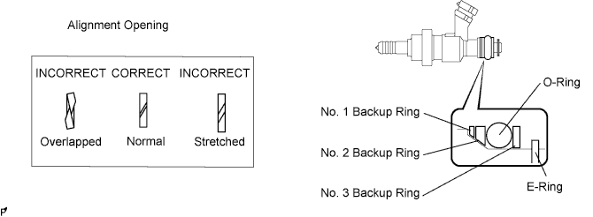
Check that the alignment openings of the backup rings are not overlapped or stretched as shown in the illustration.
-
After installing the O-ring, check that it is not contaminated with foreign matter and is not damaged.
-
-
Apply engine oil to the O-ring.
Note
Make sure there is no gasoline on the O-ring and inside the installation hole.
-
Install the 2 fuel pipe support sub-assemblies to the fuel delivery pipe and No. 2 fuel delivery pipe with the 4 bolts.
- Torque:
- 10 N*m { 102 kgf*cm, 7 ft.*lbf }
-
-
INSTALL FUEL INJECTOR SEAL
-
Apply engine conditioner to the clean area shown in the illustration. Using a piece of cloth, clean carbon deposits from the fuel injector assembly and its grooves.
Note
-
Do not clean the tip of the fuel injector assembly.
-
Do not use a wire brush to clean the fuel injector assembly.
-
If a fuel injector assembly is dropped or the tip of a fuel injector assembly is struck, replace it with a new one.
-
-
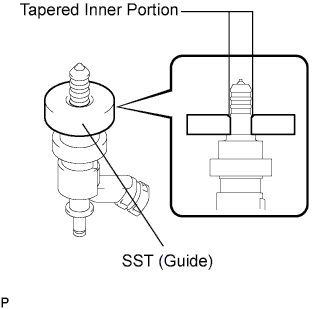
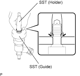
Apply engine oil to the fuel injector assembly contact surface of SST (guide). Then attach SST (guide) to the fuel injector assembly with the tapered inner portion facing the tip of the fuel injector assembly as shown in the illustration.
- SST
- 09260-39015 ( 09268-03020 )
-
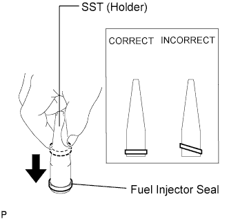
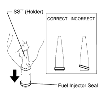
Install a new fuel injector seal to SST (holder).
- SST
- 09260-39015 ( 09268-03010 )
Note
Be careful not to install the fuel injector seal to SST (holder) at an angle. Doing so will stretch the seal and correcting this problem is very complicated.
-
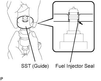
Install SST (holder with fuel injector seal) to the tip of the fuel injector assembly. Slide the seal downward into the fuel injector assembly groove (fuel injector assembly connector side) with your fingers as shown in the illustration.
- SST
- 09260-39015 ( 09268-03010, 09268-03020 )
Tech Tips
Check that the seal covers the circumference of the fuel injector assembly groove as shown in the illustration.
-
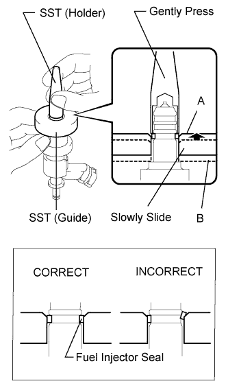
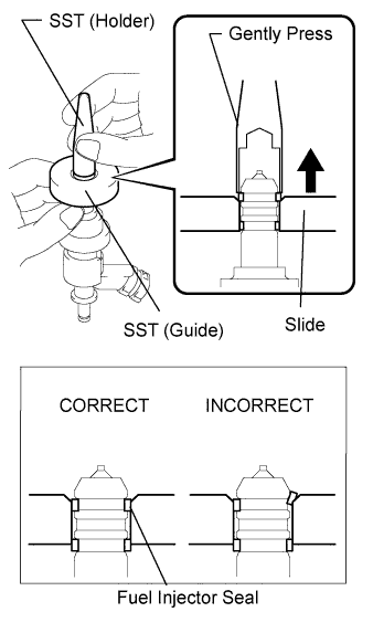
Using SST (holder), gently press downward on the fuel injector seal (fuel injector assembly connector side). Then slowly slide SST (guide) towards the fuel injector assembly tip to settle the seal into the fuel injector assembly groove.
- SST
- 09260-39015 ( 09268-03010, 09268-03020 )
Note
Be careful that the fuel injector seal is not pinched between SST (guide) and the fuel injector assembly groove. Replace the fuel injector seal if it becomes damaged.
Tech Tips
-
When using SST (guide) to settle the fuel injector seal into the groove, SST (guide) only needs to be slid upward to the position labeled A in the illustration.
-
After using SST (guide) to settle the fuel injector seal into the groove, return SST (guide) to its position labeled B in the illustration.
-
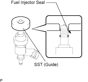
Install a new fuel injector seal to SST (holder).
- SST
- 09260-39015 ( 09268-03010 )
Note
Be careful not to install the fuel injector seal to SST (holder) at an angle. Doing so will stretch the fuel injector seal and correcting this problem is very complicated.
-
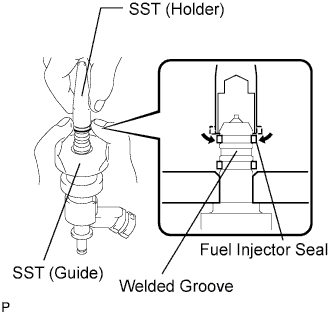
Install SST (holder with fuel injector seal) to the tip of the fuel injector assembly. Slide the seal downward into the fuel injector assembly groove (injector tip side) with your fingers as shown in the illustration.
- SST
- 09260-39015 ( 09268-03010, 09268-03020 )
Note
Make sure that the seal does not slip into the welded groove of the fuel injector assembly shown in the illustration. If it does, replace it with a new one.
Tech Tips
Check that the seal covers the circumference of the fuel injector assembly groove as shown in the illustration.
-
Slowly slide SST (guide) towards the tip of the fuel injector assembly. When the fuel injector assembly contact surface of SST (guide) aligns with the fuel injector seal (fuel injector assembly connector side) as shown in the illustration, hold the position for 5 seconds or more to fully align the seal into the fuel injector assembly groove.
- SST
- 09260-39015 ( 09268-03020 )
Note
Be careful that the fuel injector seal is not pinched between SST (guide) and the fuel injector assembly groove. Replace the fuel injector seal if it becomes damaged.
Tech Tips
-
Set SST (guide) so that its bottom surface and fuel injector seal are flush.
-
If it is difficult to slide SST upward, slowly wiggle it from side to side while sliding it up the fuel injector assembly little by little.
-
Using SST (holder), gently press downward on the fuel injector seal (fuel injector assembly tip side). Then slowly slide SST (guide) towards the fuel injector assembly tip to settle the fuel injector seal into the fuel injector assembly groove.
- SST
- 09260-39015 ( 09268-03010, 09268-03020 )
Note
Be careful that the fuel injector seal is not pinched between SST (guide) and the fuel injector assembly groove. Replace the fuel injector seal if it becomes damaged.
-
Slowly slide SST (guide) towards the tip of the fuel injector assembly. When the fuel injector assembly contact surface of SST (guide) aligns with the fuel injector seal (fuel injector assembly tip side) as shown in the illustration, hold the position for 5 seconds or more to fully align the fuel injector seal into the fuel injector assembly groove.
- SST
- 09260-39015 ( 09268-03020 )
Note
Be careful that the fuel injector seal is not pinched between SST (guide) and the fuel injector assembly groove. Replace the fuel injector seal if it becomes damaged.
Tech Tips
-
Set SST (guide) so that its bottom surface and the fuel injector seal bottom surface are flush.
-
If it is difficult to slide SST upward, slowly wiggle it from side to side while sliding it up the fuel injector assembly little by little.
-
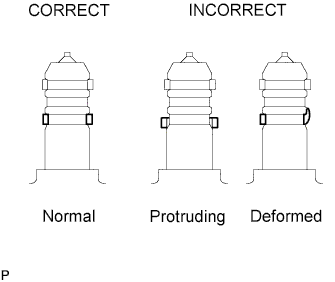
After installing the seals, check that the seals are not scratched, deformed or protruding from the fuel injector assembly grooves.
Note
If any seal is scratched, deformed or protruding from the groove, replace it with a new one.
-
-
INSTALL FUEL INJECTOR ASSEMBLY (for Direct Injection)
-
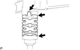
Install a new O-ring, new backup rings (No. 1, No. 2 and No. 3) and a new E-ring to the fuel injector assembly as shown in the illustration.
Note
-
Check that there is no foreign matter or damaged areas in the injector O-ring groove.
-
Check that the No. 1 and No. 2 backup rings are installed in the correct direction.
-
Make sure that the backup rings and O-ring are installed in the correct order.
-
Check that the alignment openings of the backup rings are not overlapped or stretched as shown in the illustration.
-
After installing the O-ring, check that it is not contaminated with foreign matter or damaged.
-
-
Install the nozzle holder clamp.
-
Apply engine oil to the O-ring. Install the nozzle holder clamp by aligning the protruding part of the clamp to the notch of the delivery pipe.
Note
-
Make sure that there is no gap between the delivery pipe and clamp.
-
Check that there is no foreign matter or damage to the injector insertion hole of the delivery pipe.
-
Insert the injector straight into the delivery pipe without tilting it.
-
-
-
-
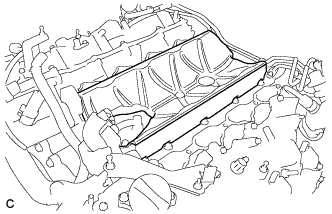
INSTALL NO. 2 FUEL DELIVERY PIPE (for Direct Injection)
-
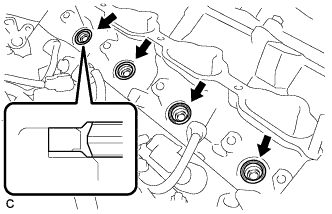
Install 4 new injector vibration insulators to the cylinder head.
-
Apply lubricant to the installation surfaces of the fuel injector seal and fuel injector assembly holes.
-
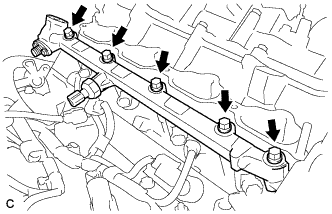
Install the No. 2 fuel delivery pipe (with fuel injector assembly) to the cylinder head with the 5 bolts.
- Torque:
- 21 N*m { 214 kgf*cm, 15 ft.*lbf }
Note
-
If a fuel injector assembly is dropped or the tip of a fuel injector assembly is struck, replace it with a new one.
-
Check that there is no foreign matter or damage to the fuel injector assembly insertion hole of the cylinder head.
-
When inserting the fuel delivery pipe, push it in evenly without tilting it.
-
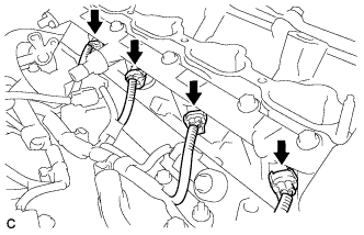
Connect the 4 injector connectors.
-
-
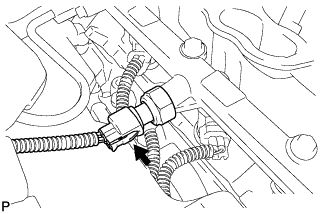
INSTALL FUEL DELIVERY PIPE (for Direct Injection)
-
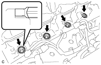
Install 4 new injector vibration insulators to the cylinder head.
-
Apply lubricant to the installation surface of the fuel injector seal and fuel injector assembly holes.
-
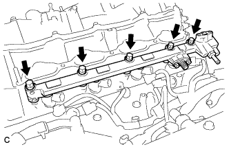
Install the fuel delivery pipe (with fuel injector assembly) to the cylinder head with the 5 bolts.
- Torque:
- 21 N*m { 214 kgf*cm, 15 ft.*lbf }
Note
-
If a fuel injector assembly is dropped or the tip of a fuel injector assembly is struck, replace it with a new one.
-
Check that there is no foreign matter or damage to the fuel injector assembly insertion hole of the cylinder head.
-
When inserting the fuel delivery pipe, push it in evenly without tilting it.
-
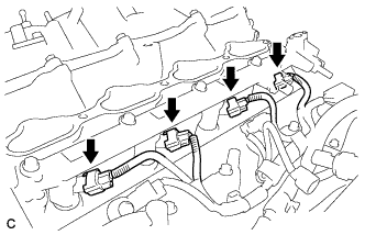
Connect the 4 injector connectors.
-
-
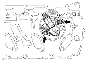
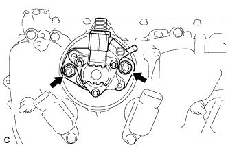
INSTALL SEPARATOR CASE
-
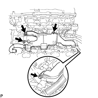
Install separator case to the cylinder head with the 4 bolts.
- Torque:
- 10 N*m { 102 kgf*cm, 7 ft.*lbf }
-
Connect the fuel pressure sensor connector.
-
-
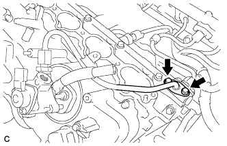
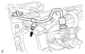
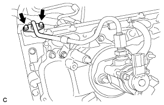
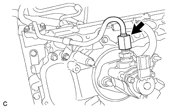
INSTALL NO. 4 FUEL PIPE SUB-ASSEMBLY
-
Temporarily install the No. 4 fuel pipe sub-assembly.
-
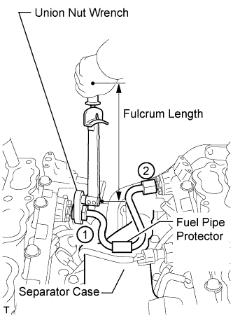
Using a 19 mm union nut wrench, tighten the No. 4 fuel pipe sub-assembly in the order shown in the illustration.
- Torque:
- without a union nut wrench
- 30 N*m { 306 kgf*cm, 22 ft.*lbf }
- with a union nut wrench
- 27 N*m { 275 kgf*cm, 20 ft.*lbf }
Note
After installing the No. 4 fuel pipe sub-assembly, check that the No. 4 fuel pipe sub-assembly protector contacts the separator case.
Tech Tips
-
Use a torque wrench with a fulcrum length of 30 cm (11.8 in.).
-
Make sure that the union nut wrench and torque wrench are connected in a straight line.
-
-
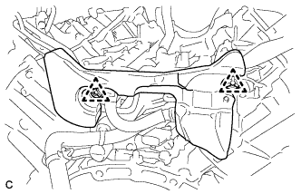
INSTALL NO. 2 ENGINE COVER SUB-ASSEMBLY LH
-
Install the No. 2 engine cover sub-assembly LH.
-
-
INSTALL NO. 1 ENGINE COVER SUB-ASSEMBLY
-
Install the No. 1 engine cover sub-assembly.
-
-
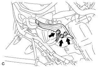
INSTALL NO. 3 FUEL PIPE SUB-ASSEMBLY
-
Install a new O-ring, new backup rings (No. 1 and No. 2) and a new E-ring to the No. 3 fuel pipe sub-assembly as shown in the illustration.
Note
-
Check that there is no foreign matter or damaged areas in the No. 3 fuel pipe sub-assembly O-ring groove.
-
Check that the No. 1 and No. 2 backup rings are installed in the correct direction.
-
Make sure that the backup rings and O-ring are installed in the correct order.
-
Check that the alignment openings of the backup rings are not overlapped or stretched as shown in the illustration.
-
After installing the O-ring, check that it is not contaminated with foreign matter or damaged.
-
-
Temporarily install the No. 3 fuel pipe sub-assembly to the delivery pipe with the 2 bolts.
-
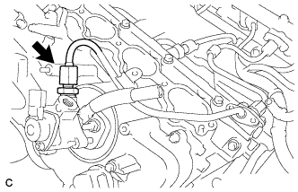
Temporarily install the No. 3 fuel pipe sub-assembly to the fuel pump assembly.
Note
Be careful not to damage the sealing surface of the fuel pipe when temporarily installing the No. 3 fuel pipe sub-assembly.
-
Install the No. 3 fuel pipe sub-assembly to the delivery pipe with the 2 bolts and tighten them in several passes.
- Torque:
- 10 N*m { 102 kgf*cm, 7 ft.*lbf }
-
Install the fuel pump assembly with the 2 nuts and tighten them in several passes.
- Torque:
- 25 N*m { 255 kgf*cm, 18 ft.*lbf }
-
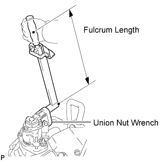
Using a 19 mm union nut wrench, tighten the union nut.
- Torque:
- without a union nut wrench
- 30 N*m { 306 kgf*cm, 22 ft.*lbf }
- with a union nut wrench
- 27 N*m { 275 kgf*cm, 20 ft.*lbf }
Note
There must be absolutely no free play in the union on the fuel pump assembly side. If the union on the fuel pump assembly side has free play, replace the fuel pump assembly.
Tech Tips
-
Use a torque wrench with a fulcrum length of 30 cm (11.8 in.).
-
Make sure that the union nut wrench and torque wrench are connected in a straight line.
-
Connect the connector to the fuel pump assembly.
-
-
INSTALL NO. 2 FUEL PIPE SUB-ASSEMBLY
-
Install a new O-ring, new backup rings (No. 1 and No. 2) and a new E-ring to the No. 2 fuel pipe subassembly as shown in the illustration.
Note
-
Check that there is no foreign matter or damaged areas in the No. 2 fuel pipe sub-assembly O-ring groove.
-
Check that the No. 1 and No. 2 backup rings are installed in the correct direction.
-
Make sure that the backup rings and O-ring are installed in the correct order.
-
Check that the alignment openings of the backup rings are not overlapped or stretched as shown in the illustration.
-
After installing the O-ring, check that it is not contaminated with foreign matter or damaged.
-
-
Temporarily install the No. 2 fuel pipe to the cylinder head cover with the bolt.
-
Temporarily install the No. 2 fuel pipe sub-assembly to the delivery pipe with the 2 bolts.
-
Temporarily install the No. 2 fuel pipe sub-assembly to the fuel pump assembly.
Note
Be careful not to damage the sealing surface of the fuel pipe when temporarily installing the No. 2 fuel pipe sub-assembly.
-
Install the No. 2 fuel pipe to the delivery pipe with the 2 bolts and tighten them in several passes.
- Torque:
- 10 N*m { 102 kgf*cm, 7 ft.*lbf }
-
Install the fuel pump assembly with the 2 nuts and tighten them in several passes.
- Torque:
- 25 N*m { 255 kgf*cm, 18 ft.*lbf }
-
Using a 19 mm union nut wrench, tighten the union nut.
- Torque:
- without a union nut wrench
- 30 N*m { 306 kgf*cm, 22 ft.*lbf }
- with a union nut wrench
- 27 N*m { 275 kgf*cm, 20 ft.*lbf }
Note
There must be absolutely no free play in the union on the fuel pump assembly side. If the union on the fuel pump assembly side has free play, replace the fuel pump assembly.
Tech Tips
-
Use a torque wrench with a fulcrum length of 30 cm (11.8 in.).
-
Make sure that the union nut wrench and torque wrench are connected in a straight line.
-
Install the No. 2 fuel pipe sub-assembly to the cylinder head cover with the bolt.
- Torque:
- 10 N*m { 102 kgf*cm, 7 ft.*lbf }
-
Connect the connector to the fuel pump assembly.
-
-
INSTALL FUEL PRESSURE PULSATION DAMPER ASSEMBLY (for Direct Injection)
-
Install the 2 fuel pressure pulsation damper assemblies and No. 1 fuel pipe sub-assembly Click here.
-
-
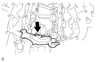
INSTALL NO. 3 COVER SUB-ASSEMBLY
-
Install the No. 3 cover sub-assembly with the 2 clips.
-
Install the bracket and wire harness with the 3 bolts.
- Torque:
- 10 N*m { 102 kgf*cm, 7 ft.*lbf }
-
-
INSTALL ENGINE WIRE
-
Connect the harness clamp then install the engine wire.
-
-
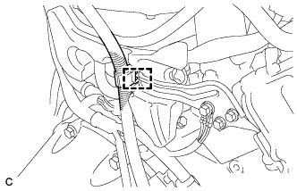
CONNECT NO. 1 FUEL HOSE
-

Push in the fuel tube connector to the No. 1 fuel hose until the fuel tube connector makes a "click" sound.
Note
-
Check that there is no damage or foreign objects on the fuel pipe connectors.
-
After connecting, check that the fuel tube connector and the pipe are securely connected by pulling on them.
-
-
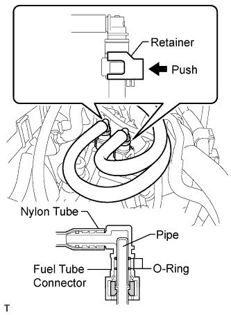
Push in the fuel tube connector to the No. 1 fuel hose until the fuel tube connector makes a "click" sound.
-
Push down on the retainer to lock it in place.
Note
-
Check that there is no damage or foreign objects on the fuel pipe connectors.
-
After connecting, check that the fuel tube connector and the pipe are securely connected by pulling on them.
-
-
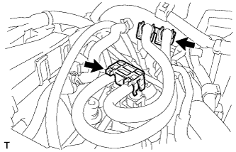
Install the 2 fuel pipe clamps.
-
-
INSTALL INTAKE AIR SURGE TANK ASSEMBLY
-
Install the intake air surge tank assembly Click here.
-
-
CONNECT CABLE TO NEGATIVE BATTERY TERMINAL
Note
When disconnecting the cable, some systems need to be initialized after the cable is reconnected Click here.
-
INSPECT FOR FUEL LEAK
-
Check fuel pump operation.
-
Connect the intelligent tester to the DLC3.
-
Turn the engine switch on (IG).
Note
Do not start the engine.
-
Turn the intelligent tester on.
-
Enter the following menus: Powertrain / Engine / Active Test / Control the Fuel Pump / Speed.
-
Check for pressure in the fuel inlet tube from the fuel line. Check that sounds of fuel flowing in the fuel tank can be heard. If no sounds can be heard, check the instrument panel junction block, fuel pump, ECM and wiring connectors.
-
-
Inspect for fuel leaks.
-
Check that there are no fuel leaks from the fuel system after performing any maintenance. If there is a fuel leak, repair or replace parts as necessary.
-
-
Turn the engine switch off.
-
Disconnect the intelligent tester from the DLC3.
-