CYLINDER HEAD REPLACEMENT

-
REPLACE INTAKE VALVE GUIDE BUSH
-
Heat the cylinder head sub-assembly to approximately 80 to 100°C (176 to 212°F).
-
Place the cylinder head sub-assembly on wooden blocks.
-
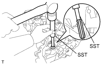
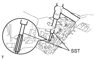
Using SST and a hammer, tap out the intake valve guide bush.
- SST
- 09201-10000 ( 09201-01050 )
- 09950-70010 ( 09951-07100 )
-
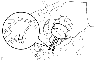
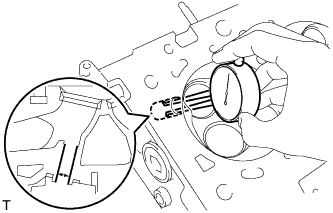
Using a caliper gauge, measure the bush bore diameter of the cylinder head side.
Standard cylinder bore diameter 10.285 to 10.306 mm (0.405 to 0.406 in.) If the bush bore diameter of the cylinder head sub-assembly is between 10.285 and 10.306 mm (0.405 and 0.406 in.), proceed to the next step.
If the bush bore diameter of the cylinder head sub-assembly is 10.356 mm (0.408 in.) or more, replace the cylinder head sub-assembly.
-
Select a new intake valve guide bush (STD or O/S 0.05), and measure its diameter.
-
Machine the bush bore diameter of the cylinder head sub-assembly to the diameter of the selected intake valve guide bush.
Bush Bore Diameter Bush Size Specified Condition STD 10.285 to 10.306 mm (0.405 to 0.406 in.) O/S 0.05 10.335 to 10.356 mm (0.407 to 0.408 in.) -
Heat the cylinder head sub-assembly to approximately 80 to 100°C (176 to 212°F).
-
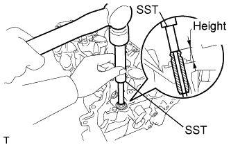
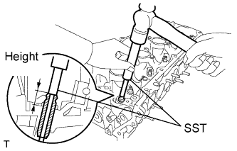
Using SST and a hammer, tap in a new intake valve guide bush to the specified protrusion height.
- SST
- 09201-10000 ( 09201-01050 )
- 09950-70010 ( 09951-07100 )
Standard protrusion height 14.3 to 14.7 mm (0.563 to 0.579 in.) -
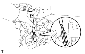
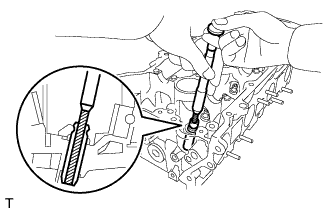
Using a sharp 5.5 mm reamer, ream the intake valve guide bush to obtain the specified clearance between the intake valve guide bush and valve stem.
-
-
REPLACE EXHAUST VALVE GUIDE BUSH
-
Heat the cylinder head sub-assembly to approximately 80 to 100°C (176 to 212°F).
-
Place the cylinder head sub-assembly on wooden blocks.
-
Using SST and a hammer, tap out the exhaust valve guide bush.
- SST
- 09201-10000 ( 09201-01050 )
- 09950-70010 ( 09951-07100 )
-
Using a caliper gauge, measure the bush bore diameter of the cylinder head side.
Standard cylinder bore diameter 10.285 to 10.306 mm (0.405 to 0.406 in.)
-
If the bush diameter of the cylinder head is between 10.285 and 10.306 mm (0.405 and 0.406 in.), proceed to the next step.
-
If the bush bore diameter of the cylinder head is 10.356 mm (0.408 in.) or more, replace the cylinder head.
-
-
Select a new exhaust valve guide bush (STD or O/S 0.05), and measure its diameter.
-
Machine the bush bore diameter of the cylinder head side to the diameter of the selected exhaust valve guide bush.
Bush Bore Diameter Bush Size Specified Condition STD 10.285 to 10.306 mm (0.405 to 0.406 in.) O/S 0.05 10.335 to 10.356 mm (0.407 to 0.408 in.) -
Heat the cylinder head sub-assembly to approximately 80 to 100°C (176 to 212°F).
-
Using SST and a hammer, tap in a new exhaust valve guide bush to the specified protrusion height.
- SST
- 09201-10000 ( 09201-01050 )
- 09950-70010 ( 09951-07100 )
Standard protrusion height 14.3 to 14.7 mm (0.563 to 0.579 in.) -
Using a sharp 5.5 mm reamer, ream the exhaust valve guide bush to obtain the specified clearance between the exhaust valve guide bush and valve stem.
-
-
REPLACE STRAIGHT PIN
Note
It is not necessary to remove the straight pins unless they are being replaced.
-
Remove the straight pins.
-
Using a plastic-faced hammer, tap in new straight pins until they stop.
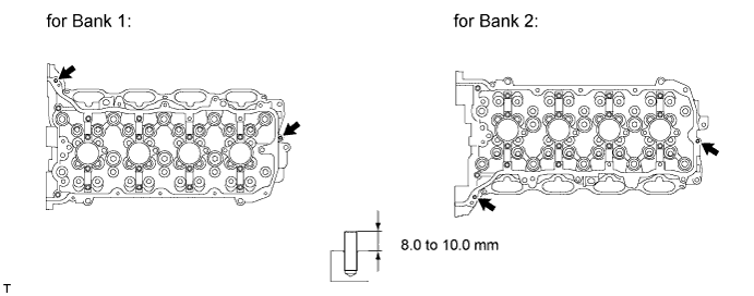
Standard protrusion 8.0 to 10.0 mm (0.315 to 0.394 in.)
-
-
REPLACE STUD BOLT
Note
If a stud bolt is deformed or the threads are damaged, replace it.
-
Remove the stud bolts.
-
Using E6 and E8 "TORX" socket wrenches, install the stud bolts.
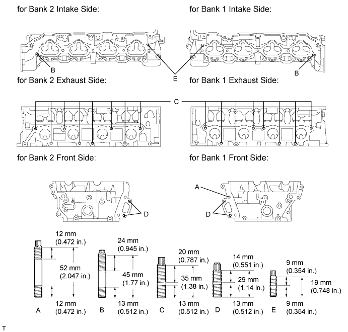
- Torque:
- Bolt A,B,C and D
- 9.0 N*m { 92 kgf*cm, 80 in.*lbf }
- Bolt E
- 5.0 N*m { 51 kgf*cm, 44 in.*lbf }
-