ENGINE UNIT INSTALLATION

-
INSTALL NO. 3 V-BANK COVER BRACKET SUB-ASSEMBLY
-
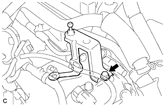
Install the No. 3 V-bank cover bracket sub-assembly with the bolt.
- Torque:
- 10 N*m { 102 kgf*cm, 7 ft.*lbf }
-
-
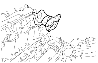
INSTALL NO. 4 V-BANK COVER BRACKET SUB-ASSEMBLY
-
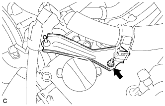
Install the No. 4 V-bank cover bracket sub-assembly with the nut.
- Torque:
- 10 N*m { 102 kgf*cm, 7 ft.*lbf }
-
-
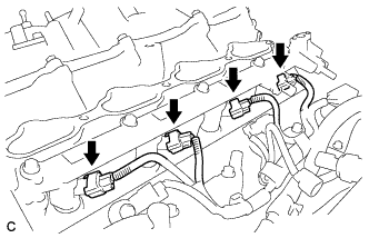
INSTALL IGNITION COIL ASSEMBLY
-
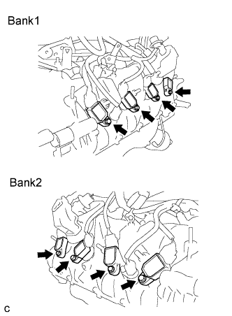
Install the 8 ignition coil assemblies with the 8 bolts.
Note
Do not damage the ignition coil assemblies when installing them.
- Torque:
- 9.0 N*m { 92 kgf*cm, 80 in.*lbf }
-
Connect the 8 ignition coil connectors.
-
-
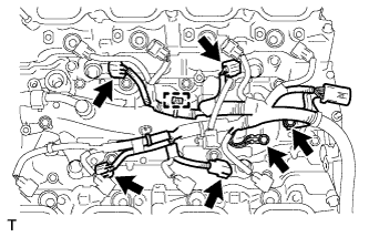
INSTALL KNOCK SENSOR
-
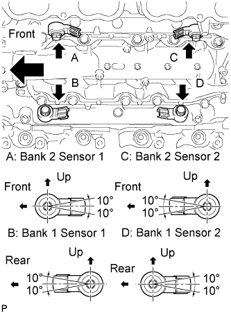
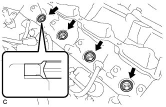
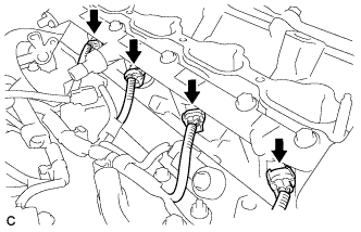
Install the 4 knock control sensors with the 4 bolts so that the sensors are angled as shown in the illustration.
- Torque:
- 20 N*m { 204 kgf*cm, 15 ft.*lbf }
Note
The acceptable installation angle of the knock control sensors is within +/- 10° from the horizontal position.
-
Connect the 4 knock control sensor connectors.
-
-
INSTALL E.F.I. ENGINE COOLANT TEMPERATURE SENSOR
-
Install a new gasket to the E.F.I. engine coolant temperature sensor.
-
Install the E.F.I engine coolant temperature sensor.
- Torque:
- 21 N*m { 214 kgf*cm, 15 ft.*lbf }
-
Connect the E.F.I. engine coolant temperature sensor connector.
-
-
INSTALL ENGINE OIL LEVEL SENSOR
-
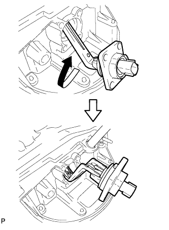
Install a new gasket to the engine oil level sensor.
-
Insert the engine oil level sensor into the oil pan sub-assembly and rotate it 180° clockwise.
-
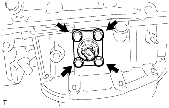
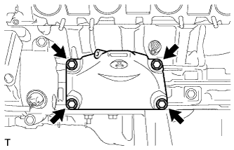
Install the engine oil level sensor with the 4 bolts.
- Torque:
- 7.0 N*m { 71 kgf*cm, 62 in.*lbf }
-
Connect the engine oil level sensor connector.
-
-
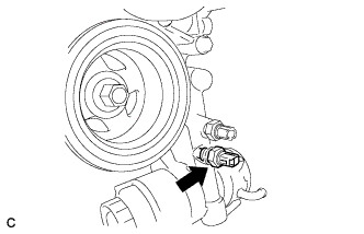
INSTALL OIL TEMPERATURE SENSOR
-
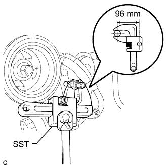
Using SST, install the oil temperature sensor with a new gasket.
- SST
- 09922-10010
- Torque:
- without SST
- 39 N*m { 400 kgf*cm, 29 ft.*lbf }
- Torque:
- with SST
- 30 N*m { 301 kgf*cm, 22 ft.*lbf }
Note
-
The "with SST" torque value is effective when using SST with a fulcrum length of 52 mm (2.05 in.).
-
The "with SST" torque value is effective when using a torque wrench with a fulcrum length of 300 mm (11.81 in.) Click here.
-
The "with SST" torque value is effective when SST is parallel to the torque wrench.
-
Do not subject the oil temperature sensor to any impacts.
-
If the sensor is subjected to an impact, replace the oil temperature sensor with a new one.
-
Do not allow any moisture or foreign matter to enter the oil temperature sensor or its connector.
-
Connect the oil temperature sensor connector.
-
-
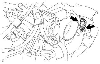
INSTALL ENGINE OIL PRESSURE SWITCH ASSEMBLY
-
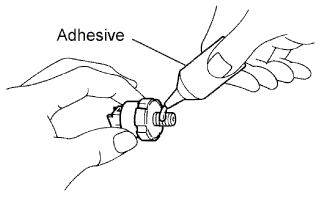
Apply adhesive to 2 or 3 threads of the oil pressure switch.
Adhesive Toyota Genuine Adhesive 1344, Three Bond 1344 or equivalent -
Using a deep socket wrench (24mm), install the oil pressure switch.
- Torque:
- 15 N*m { 153 kgf*cm, 11 ft.*lbf }
Note
Do not start the engine for at least 1 hour after installing the switch.
-
-
INSTALL NO. 2 WATER BY-PASS PIPE SUB-ASSEMBLY
-
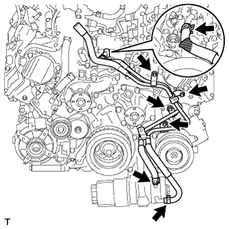
Install the No. 2 water by-pass pipe sub-assembly with the 4 bolts.
- Torque:
- 10 N*m { 102 kgf*cm, 7 ft.*lbf }
-
Connect the 3 water by-pass hoses with the 3 hose clamps.
-
-
INSTALL INLET WATER HOUSING
-
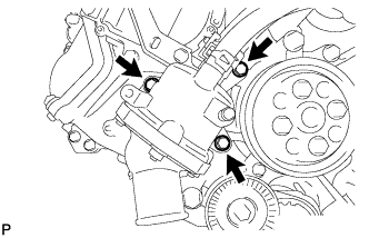
Install the inlet water housing and a new gasket with the 3 bolts.
- Torque:
- 21 N*m { 214 kgf*cm, 15 ft.*lbf }
-
Connect the inlet water hose with the hose clamp.
-
-
INSTALL WATER PUMP PULLEY
-
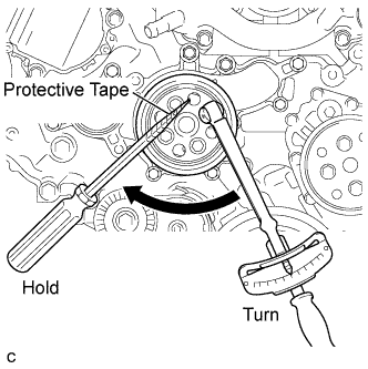
Temporarily install the pulley with the 4 bolts.
-
Using a screwdriver or an equivalent, hold the pulley and tighten the 4 bolts.
- Torque:
- 21 N*m { 214 kgf*cm, 15 ft.*lbf }
Tech Tips
Tape the screwdriver tip before use to avoid damage.
-
-
INSTALL OIL PUMP DRIVE SHAFT PULLEY
-
Temporarily install the oil pump drive shaft pulley with the 4 bolts.
-
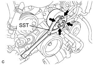
Using SST, hold the oil pump drive shaft pulley and tighten the 4 bolts.
- SST
- 09960-10010 ( 09962-01000, 09963-00600 )
- Torque:
- 23 N*m { 235 kgf*cm, 17 ft.*lbf }
-
-
INSTALL NO. 2 IDLER PULLEY SUB-ASSEMBLY
-
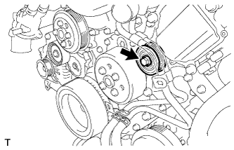
Install the bolt and idler pulley.
- Torque:
- 43 N*m { 439 kgf*cm, 32 ft.*lbf }
-
-
INSTALL NO. 4 ENGINE COVER SUB-ASSEMBLY
-
Install the engine cover.
-
-
INSTALL NO. 5 ENGINE WIRE
-
Install the engine wire with the 2 bolts.
- Torque:
- 10 N*m { 102 kgf*cm, 7 ft.*lbf }
-
Connect the 4 knock sensor connectors.
-
-
INSTALL FUEL INJECTOR SEAL
-
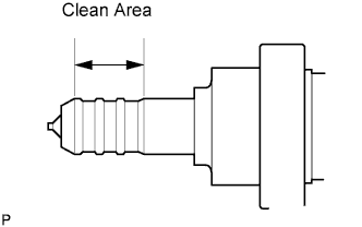
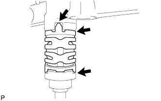
Apply engine conditioner to the clean area shown in the illustration. Using a piece of cloth, clean carbon deposits from the fuel injector assembly and its grooves.
Note
-
Do not clean the tip of the fuel injector assembly.
-
Do not use a wire brush to clean the fuel injector assembly.
-
If a fuel injector assembly is dropped or the tip of a fuel injector assembly is struck, replace it with a new one.
-
-
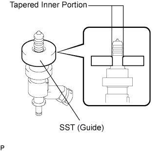
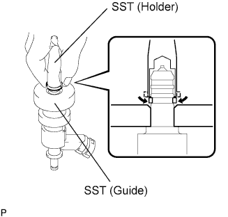
Apply engine oil to the fuel injector assembly contact surface of SST (guide). Then attach SST (guide) to the fuel injector assembly with the tapered inner portion facing the tip of the fuel injector assembly as shown in the illustration.
- SST
- 09260-39015 ( 09268-03020 )
-
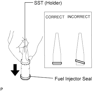
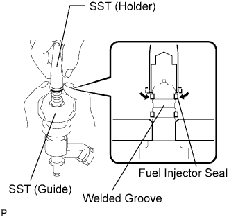
Install a new fuel injector seal to SST (holder).
- SST
- 09260-39015 ( 09268-03010 )
Note
Be careful not to install the fuel injector seal to SST (holder) at an angle. Doing so will stretch the seal and correcting this problem is very complicated.
-
Install SST (holder with fuel injector seal) to the tip of the fuel injector assembly. Slide the seal downward into the fuel injector assembly groove (fuel injector assembly connector side) with your fingers as shown in the illustration.
- SST
- 09260-39015 ( 09268-03010, 09268-03020 )
Tech Tips
Check that the seal covers the circumference of the fuel injector assembly groove as shown in the illustration.
-
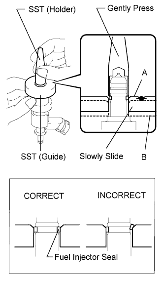
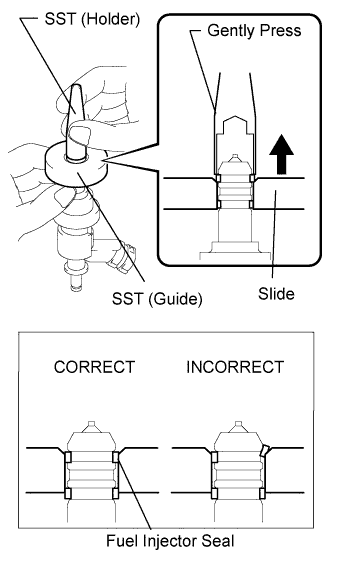
Using SST (holder), gently press downward on the fuel injector seal (fuel injector assembly connector side). Then slowly slide SST (guide) towards the fuel injector assembly tip to settle the seal into the fuel injector assembly groove.
- SST
- 09260-39015 ( 09268-03010, 09268-03020 )
Note
Be careful that the fuel injector seal is not pinched between SST (guide) and the fuel injector assembly groove. Replace the fuel injector seal if it becomes damaged.
Tech Tips
-
When using SST (guide) to settle the fuel injector seal into the groove, SST (guide) only needs to be slid upward to the position labeled A in the illustration.
-
After using SST (guide) to settle the fuel injector seal into the groove, return SST (guide) to its position labeled B in the illustration.
-
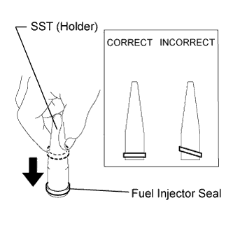
Install a new fuel injector seal to SST (holder).
- SST
- 09260-39015 ( 09268-03010 )
Note
Be careful not to install the fuel injector seal to SST (holder) at an angle. Doing so will stretch the fuel injector seal and correcting this problem is very complicated.
-
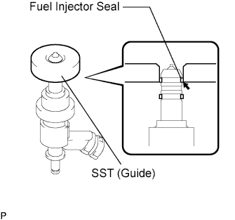
Install SST (holder with fuel injector seal) to the tip of the fuel injector assembly. Slide the seal downward into the fuel injector assembly groove (injector tip side) with your fingers as shown in the illustration.
- SST
- 09260-39015 ( 09268-03010, 09268-03020 )
Note
Make sure that the seal does not slip into the welded groove of the fuel injector assembly shown in the illustration. If it does, replace it with a new one.
Tech Tips
Check that the seal covers the circumference of the fuel injector assembly groove as shown in the illustration.
-
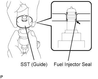
Slowly slide SST (guide) towards the tip of the fuel injector assembly. When the fuel injector assembly contact surface of SST (guide) aligns with the fuel injector seal (fuel injector assembly connector side) as shown in the illustration, hold the position for 5 seconds or more to fully align the seal into the fuel injector assembly groove.
- SST
- 09260-39015 ( 09268-03020 )
Note
Be careful that the fuel injector seal is not pinched between SST (guide) and the fuel injector assembly groove. Replace the fuel injector seal if it becomes damaged.
Tech Tips
-
Set SST (guide) so that its bottom surface and fuel injector seal are flush.
-
If it is difficult to slide SST upward, slowly wiggle it from side to side while sliding it up the fuel injector assembly little by little.
-
Using SST (holder), gently press downward on the fuel injector seal (fuel injector assembly tip side). Then slowly slide SST (guide) towards the fuel injector assembly tip to settle the fuel injector seal into the fuel injector assembly groove.
- SST
- 09260-39015 ( 09268-03010, 09268-03020 )
Note
Be careful that the fuel injector seal is not pinched between SST (guide) and the fuel injector assembly groove. Replace the fuel injector seal if it becomes damaged.
-
Slowly slide SST (guide) towards the tip of the fuel injector assembly. When the fuel injector assembly contact surface of SST (guide) aligns with the fuel injector seal (fuel injector assembly tip side) as shown in the illustration, hold the position for 5 seconds or more to fully align the fuel injector seal into the fuel injector assembly groove.
- SST
- 09260-39015 ( 09268-03020 )
Note
Be careful that the fuel injector seal is not pinched between SST (guide) and the fuel injector assembly groove. Replace the fuel injector seal if it becomes damaged.
Tech Tips
-
Set SST (guide) so that its bottom surface and the fuel injector seal bottom surface are flush.
-
If it is difficult to slide SST upward, slowly wiggle it from side to side while sliding it up the fuel injector assembly little by little.
-
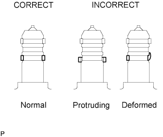
After installing the seals, check that the seals are not scratched, deformed or protruding from the fuel injector assembly grooves.
Note
If any seal is scratched, deformed or protruding from the groove, replace it with a new one.
-
-
INSTALL FUEL INJECTOR ASSEMBLY (for Direct Injection)
-
Install a new O-ring, new backup rings (No. 1, No. 2 and No. 3) and a new E-ring to the fuel injector assembly as shown in the illustration.
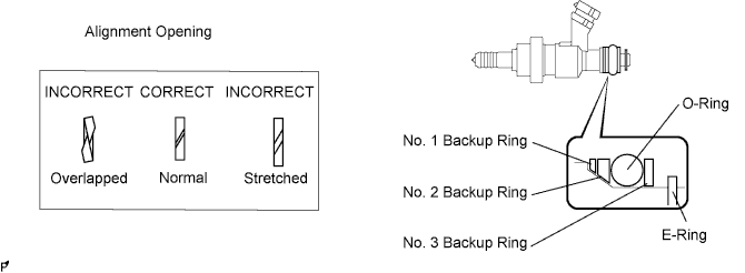
Note
-
Check that there is no foreign matter or damaged areas in the injector O-ring groove.
-
Check that the No. 1 and No. 2 backup rings are installed in the correct direction.
-
Make sure that the backup rings and O-ring are installed in the correct order.
-
Check that the alignment openings of the backup rings are not overlapped or stretched as shown in the illustration.
-
After installing the O-ring, check that it is not contaminated with foreign matter or damaged.
-
-
Install the nozzle holder clamp.
-
Apply engine oil to the O-ring. Install the nozzle holder clamp by aligning the protruding part of the clamp to the notch of the delivery pipe.
Note
-
Make sure that there is no gap between the delivery pipe and clamp.
-
Check that there is no foreign matter or damage to the injector insertion hole of the delivery pipe.
-
Insert the injector straight into the delivery pipe without tilting it.
-
-
-
-
INSTALL NO. 2 FUEL DELIVERY PIPE (for Direct Injection)
-
Install 4 new injector vibration insulators to the cylinder head.
-
Apply lubricant to the installation surfaces of the fuel injector seal and fuel injector assembly holes.
-
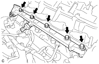
Install the No. 2 fuel delivery pipe (with fuel injector assembly) to the cylinder head with the 5 bolts.
- Torque:
- 21 N*m { 214 kgf*cm, 15 ft.*lbf }
Note
-
If a fuel injector assembly is dropped or the tip of a fuel injector assembly is struck, replace it with a new one.
-
Check that there is no foreign matter or damage to the fuel injector assembly insertion hole of the cylinder head.
-
When inserting the fuel delivery pipe, push it in evenly without tilting it.
-
Connect the 4 injector connectors.
-
-
INSTALL FUEL DELIVERY PIPE (for Direct Injection)
-
Install 4 new injector vibration insulators to the cylinder head.
-
Apply lubricant to the installation surface of the fuel injector seal and fuel injector assembly holes.
-
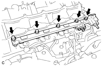
Install the fuel delivery pipe (with fuel injector assembly) to the cylinder head with the 5 bolts.
- Torque:
- 21 N*m { 214 kgf*cm, 15 ft.*lbf }
Note
-
If a fuel injector assembly is dropped or the tip of a fuel injector assembly is struck, replace it with a new one.
-
Check that there is no foreign matter or damage to the fuel injector assembly insertion hole of the cylinder head.
-
When inserting the fuel delivery pipe, push it in evenly without tilting it.
-
Connect the 4 injector connectors.
-
-
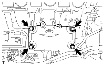
INSTALL SEPARATOR CASE
-
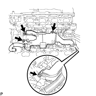
Install separator case to the cylinder head with the 4 bolts.
- Torque:
- 10 N*m { 102 kgf*cm, 7 ft.*lbf }
-
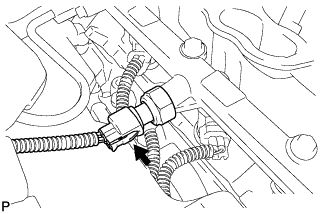
Connect the fuel pressure sensor connector.
-
-
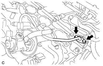
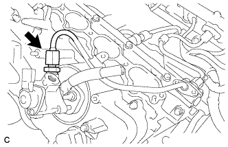
INSTALL NO. 4 FUEL PIPE SUB-ASSEMBLY
-
Temporarily install the No. 4 fuel pipe sub-assembly.
-
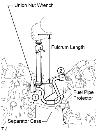
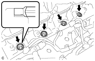
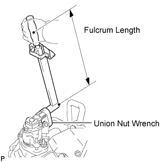
Using a 19 mm union nut wrench, tighten the No. 4 fuel pipe sub-assembly in the order shown in the illustration.
- Torque:
- without a union nut wrench
- 30 N*m { 306 kgf*cm, 22 ft.*lbf }
- with a union nut wrench
- 27 N*m { 275 kgf*cm, 20 ft.*lbf }
Note
After installing the No. 4 fuel pipe sub-assembly, check that the No. 4 fuel pipe sub-assembly protector contacts the separator case.
Tech Tips
-
Use a torque wrench with a fulcrum length of 30 cm (11.8 in.).
-
Make sure that the union nut wrench and torque wrench are connected in a straight line.
-
-
INSTALL NO. 2 ENGINE COVER SUB-ASSEMBLY LH
-
Install the No. 2 engine cover sub-assembly LH.
-
-
INSTALL NO. 1 ENGINE COVER SUB-ASSEMBLY
-
Install the No. 1 engine cover sub-assembly.
-
-
INSTALL FUEL PUMP SPACER
-
Install the 2 fuel pump spacers.
-
-
INSTALL FUEL PUMP ASSEMBLY (for Bank 1)
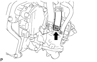
-
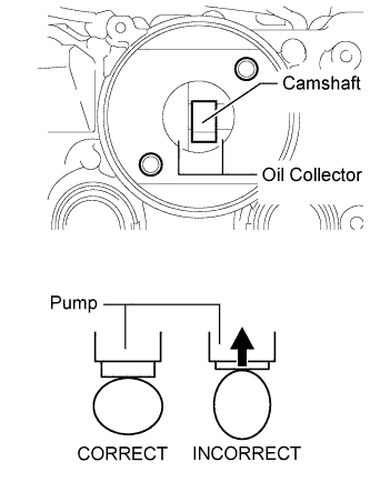
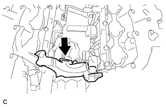
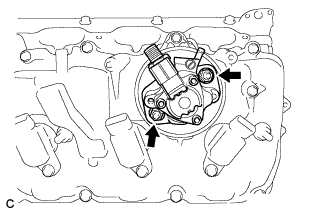
Rotate the crankshaft until the base circle of the fuel pump cam is facing the hole in the cylinder head cover as shown in the illustration.
Tech Tips
Setting the cam in this position does not compress the fuel pump plunger, making it easier to install the fuel pump assembly and No. 3 fuel pipe sub-assembly later.
-
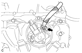
Pour 30 cm3(1.8 cu in.) of engine oil through the hole in the cylinder head cover into the cylinder head oil collector.
-
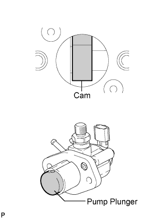
Apply a coat of engine oil to the fuel pump activation cam and pump plunger.
-
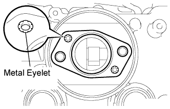
Install a new fuel pump insulator to the cylinder head cover. Then pass the 2 stud bolts through the holes of the fuel pump assembly and set them on the fuel pump insulator.
Note
Install the fuel pump insulator so that the open sides of the metal eyelets are facing outward as shown in the illustration.
-
Temporarily install the 2 nuts and fuel pump assembly.
-
Connect the fuel hose.
-
-
INSTALL NO. 3 FUEL PIPE SUB-ASSEMBLY
-
Install a new O-ring, new backup rings (No. 1 and No. 2) and a new E-ring to the No. 3 fuel pipe sub-assembly as shown in the illustration.
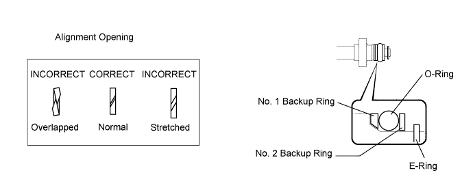
Note
-
Check that there is no foreign matter or damaged areas in the No. 3 fuel pipe sub-assembly O-ring groove.
-
Check that the No. 1 and No. 2 backup rings are installed in the correct direction.
-
Make sure that the backup rings and O-ring are installed in the correct order.
-
Check that the alignment openings of the backup rings are not overlapped or stretched as shown in the illustration.
-
After installing the O-ring, check that it is not contaminated with foreign matter or damaged.
-
-
Temporarily install the No. 3 fuel pipe sub-assembly to the delivery pipe with the 2 bolts.
-
Temporarily install the No. 3 fuel pipe sub-assembly to the fuel pump assembly.
Note
Be careful not to damage the sealing surface of the fuel pipe when temporarily installing the No. 3 fuel pipe sub-assembly.
-
Install the No. 3 fuel pipe sub-assembly to the delivery pipe with the 2 bolts and tighten them in several passes.
- Torque:
- 10 N*m { 102 kgf*cm, 7 ft.*lbf }
-
Install the fuel pump assembly with the 2 nuts and tighten them in several passes.
- Torque:
- 25 N*m { 255 kgf*cm, 18 ft.*lbf }
-
Using a 19 mm union nut wrench, tighten the union nut.
- Torque:
- without a union nut wrench
- 30 N*m { 306 kgf*cm, 22 ft.*lbf }
- with a union nut wrench
- 27 N*m { 275 kgf*cm, 20 ft.*lbf }
Note
There must be absolutely no free play in the union on the fuel pump assembly side. If the union on the fuel pump assembly side has free play, replace the fuel pump assembly.
Tech Tips
-
Use a torque wrench with a fulcrum length of 30 cm (11.8 in.).
-
Make sure that the union nut wrench and torque wrench are connected in a straight line.
-
Connect the connector to the fuel pump assembly.
-
-
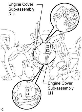
INSTALL ENGINE COVER SUB-ASSEMBLY (for Bank 1)
-
Attach the 5 claws and install the engine covers LH and RH to the fuel pump assembly.
-
-
INSTALL FUEL PUMP ASSEMBLY (for Bank 2)
Tech Tips
Use the same procedure as for the bank 1 side.
-
INSTALL NO. 2 FUEL PIPE SUB-ASSEMBLY
-
Install a new O-ring, new backup rings (No. 1 and No. 2) and a new E-ring to the No. 2 fuel pipe subassembly as shown in the illustration.
Note
-
Check that there is no foreign matter or damaged areas in the No. 2 fuel pipe sub-assembly O-ring groove.
-
Check that the No. 1 and No. 2 backup rings are installed in the correct direction.
-
Make sure that the backup rings and O-ring are installed in the correct order.
-
Check that the alignment openings of the backup rings are not overlapped or stretched as shown in the illustration.
-
After installing the O-ring, check that it is not contaminated with foreign matter or damaged.
-
-
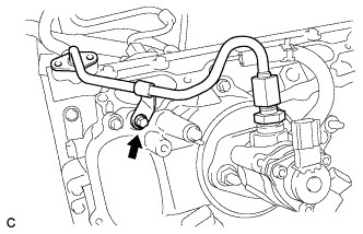
Temporarily install the No. 2 fuel pipe to the cylinder head cover with the bolt.
-
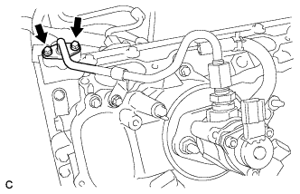
Temporarily install the No. 2 fuel pipe sub-assembly to the delivery pipe with the 2 bolts.
-
Temporarily install the No. 2 fuel pipe sub-assembly to the fuel pump assembly.
Note
Be careful not to damage the sealing surface of the fuel pipe when temporarily installing the No. 2 fuel pipe sub-assembly.
-
Install the No. 2 fuel pipe to the delivery pipe with the 2 bolts and tighten them in several passes.
- Torque:
- 10 N*m { 102 kgf*cm, 7 ft.*lbf }
-
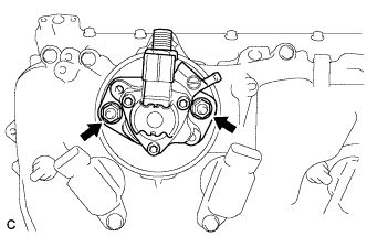
Install the fuel pump assembly with the 2 nuts and tighten them in several passes.
- Torque:
- 25 N*m { 255 kgf*cm, 18 ft.*lbf }
-
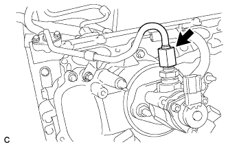
Using a 19 mm union nut wrench, tighten the union nut.
- Torque:
- without a union nut wrench
- 30 N*m { 306 kgf*cm, 22 ft.*lbf }
- with a union nut wrench
- 27 N*m { 275 kgf*cm, 20 ft.*lbf }
Note
There must be absolutely no free play in the union on the fuel pump assembly side. If the union on the fuel pump assembly side has free play, replace the fuel pump assembly.
Tech Tips
-
Use a torque wrench with a fulcrum length of 30 cm (11.8 in.).
-
Make sure that the union nut wrench and torque wrench are connected in a straight line.
-
Install the No. 2 fuel pipe sub-assembly to the cylinder head cover with the bolt.
- Torque:
- 10 N*m { 102 kgf*cm, 7 ft.*lbf }
-
Connect the connector to the fuel pump assembly.
-
-
INSTALL ENGINE COVER SUB-ASSEMBLY (for Bank 2)
Tech Tips
Use the same procedure as for the bank 1 side.
-
INSTALL FUEL PRESSURE PULSATION DAMPER ASSEMBLY (for Direct Injection)
-
Install the fuel pressure pulsation damper assembly and No. 1 fuel pipe sub-assembly Click here.
-
-
INSTALL NO. 3 COVER SUB-ASSEMBLY
-
Install the No. 3 cover sub-assembly with the 2 clips.
-
Install the bracket and wire harness with the 3 bolts.
- Torque:
- 10 N*m { 102 kgf*cm, 7 ft.*lbf }
-
-
INSTALL INTAKE AIR SURGE TANK ASSEMBLY
-
Install the union to check valve hose bracket with the bolt (for LHD).
- Torque:
- 10 N*m { 102 kgf*cm, 7 ft.*lbf }
-
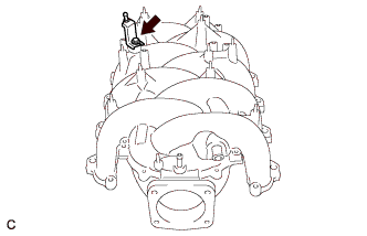
Install the V-bank cover bracket sub-assembly with the bolt.
- Torque:
- 10 N*m { 102 kgf*cm, 7 ft.*lbf }
-
Install 2 new gaskets to the intake air surge tank assembly.
-
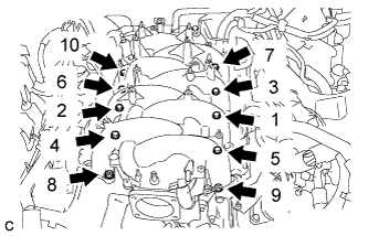
Temporarily install the intake air surge tank assembly with the 2 nuts and 8 bolts. Then tighten the 2 nuts and 8 bolts uniformly in the order shown in the illustration.
- Torque:
- 21 N*m { 214 kgf*cm, 16 ft.*lbf }
-
-
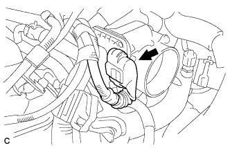
CONNECT VENTILATION HOSE
-
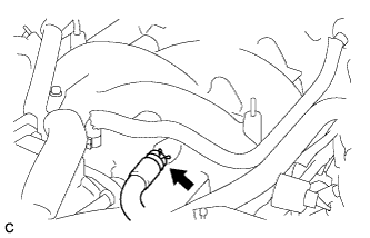
Connect the ventilation hose to the intake air surge tank sub assembly.
-
-
CONNECT WATER BY-PASS HOSE
-
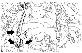
Connect the water by-pass pipe hose, No. 3 water by-pass hose and No. 9 water by-pass hose with the 3 clamps to the water by-pass pipe sub-assembly.
-
-
INSTALL INJECTOR DRIVER
Note
-
Be careful not to drop or strike the injector drivers.
-
The injector drivers are grounded at the bolt and nut. To ensure that they are grounded, remove all oil and foreign matter from the installation areas of the injector drivers and engine before installing the injector drivers.
-
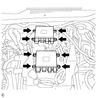
Install the 2 injector drivers to the intake air surge tank assembly with the 8 nuts.
- Torque:
- 7.5 N*m { 76 kgf*cm, 66 in.*lbf }
-
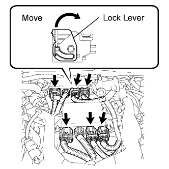
Connect the 8 injector driver connectors.
-
Connect the 6 connectors with wire harness locks and the 2 connectors without wire harness locks to the 2 injector drivers.
Note
Connect the connectors securely.
Tech Tips
Move the lock lever in the direction indicated by the arrow to lock the connectors.
-
-
-
INSTALL THROTTLE BODY ASSEMBLY
-
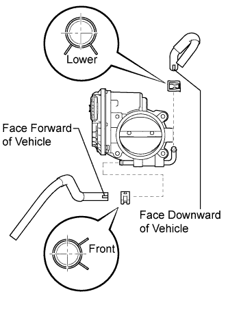
Connect the No. 4 water by-pass hose and No. 5 water by-pass hose to the throttle body assembly.
Note
Position the claws of the clamps as shown in the illustration.
-
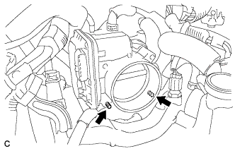
Set the throttle body assembly and new gasket with the 2 stud bolts.
-
Using a "TORX" socket E6, tighten the 2 stud bolts.
- Torque:
- 5.0 N*m { 51 kgf*cm, 44 in.*lbf }
-
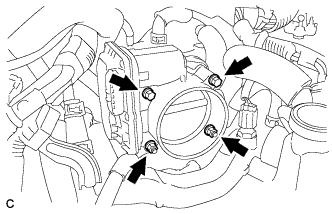
Install the 2 bolts and 2 nuts.
- Torque:
- 10 N*m { 102 kgf*cm, 7 ft.*lbf }
-
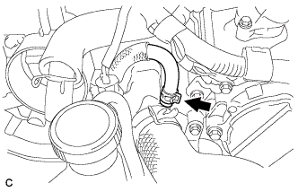
Connect the No. 4 water by-pass hose with the hose clamp.
-
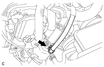
Connect the No. 5 water by-pass hose with the hose clamp.
-
Connect the throttle body connector.
-
-
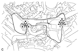
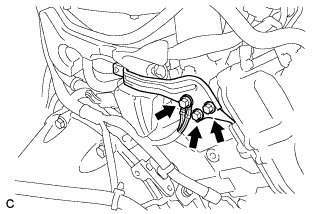
INSTALL TRANSMISSION BREATHER ASSEMBLY
-
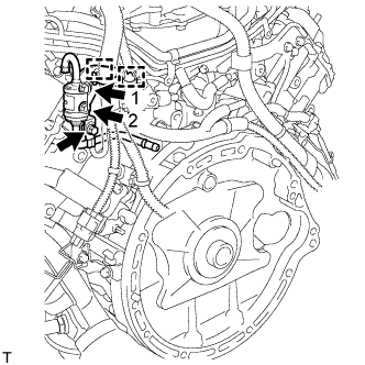
Install the 2 bolts to the transmission breather assembly in the order shown in the illustration.
- Torque:
- Bolt 1
- 7.0 N*m { 71 kgf*cm, 62 in.*lbf }
- Bolt 2
- 7.0 N*m { 71 kgf*cm, 62 in.*lbf }
Bolt Bolt Length 1 30 mm (1.18 in.) 2 14 mm (0.551 in.) Tech Tips
Be sure to install the transmission breather assembly so that the pipe is positioned between the two-way wire harness.
-
Connect the 2 wire harness clamps to the transmission breather assembly .
-
Install the bolt and ground wire to the transmission breather assembly.
- Torque:
- 10 N*m { 102 kgf*cm, 7 ft.*lbf }
-
-
INSTALL WIRE HARNESS CLAMP BRACKET
-
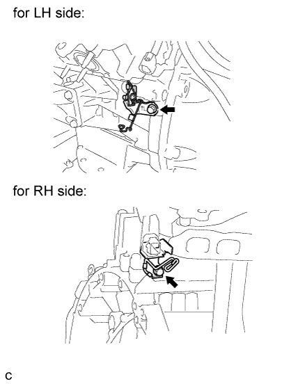
Install the 2 wire harness clamp brackets with the 2 bolts.
- Torque:
- for LH side
- 21 N*m { 214 kgf*cm, 15 ft.*lbf }
- for RH side
- 29 N*m { 296 kgf*cm, 21 ft.*lbf }
-
-
INSTALL FRONT NO. 1 ENGINE MOUNTING BRACKET RH
-
Install the mounting bracket with the 4 bolts.
- Torque:
- 35 N*m { 357 kgf*cm, 26 ft.*lbf }
-
-
INSTALL FRONT NO. 1 ENGINE MOUNTING BRACKET LH
-
Install the mounting bracket with the 4 bolts.
- Torque:
- 35 N*m { 357 kgf*cm, 26 ft.*lbf }
-
-
INSTALL ENGINE WIRE
-
Install the engine wire.
-
-
INSTALL ENGINE HANGER
-
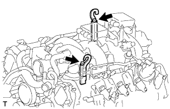
Install the 2 engine hangers with the 2 bolts as shown in the illustration.
Engine Hanger Part No. Item Part No. Engine hanger 12081-38020 Bolt 90119-14120 - Torque:
- 43 N*m { 438 kgf*cm, 32 ft.*lbf }
-
-
REMOVE ENGINE STAND
-
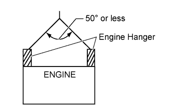
Attach an engine sling device and hang the engine with a chain block.
Note
When hanging the engine, make sure to hang the engine with the chain at an angle of 50° or less. Otherwise, the engine or engine hangers may be damaged.
-
Remove the bolts and engine assembly from the engine stand.
-