FUEL PRESSURE PULSATION DAMPER (for Port Injection) INSTALLATION

-
INSTALL FUEL PRESSURE PULSATION DAMPER ASSEMBLY (for Port Injection)
-
Temporarily install the 2 fuel pressure pulsation damper assemblies together with 4 new gaskets and the fuel tube sub-assembly.
-
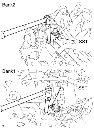
Using SST, tighten the 2 fuel pressure pulsation damper assemblies.
- SST
- 09612-24014 ( 09617-24011 )
- Torque:
- without SST
- 40 N*m { 408 kgf*cm, 30 ft.*lbf }
- with SST
- 35 N*m { 357 kgf*cm, 26 ft.*lbf }
Tech Tips
-
Use a torque wrench with a fulcrum length of 30 cm (11.81 in.).
-
Make sure that SST and the wrench are connected in a straight line.
-
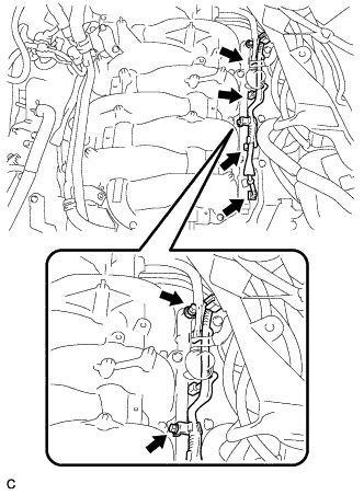
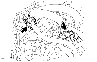
Install the wire harness with the 2 bolts.
- Torque:
- 10 N*m { 102 kgf*cm, 7 ft.*lbf }
-
Connect the 4 connectors.
-
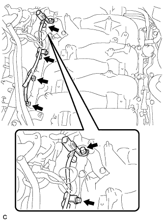
Install the wire harness with the 2 bolts.
- Torque:
- 10 N*m { 102 kgf*cm, 7 ft.*lbf }
-
Connect the 4 connectors.
-
-
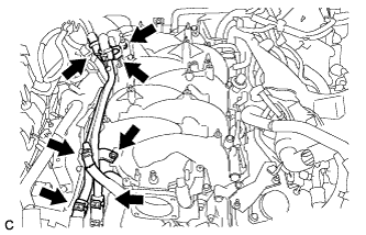
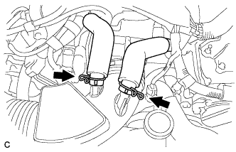
INSTALL NO. 3 FUEL HOSE
-
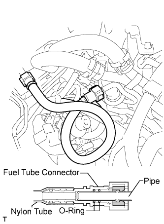
Push in the fuel tube connector to the No. 3 fuel hose until the fuel tube connector makes a "click" sound.
Note
-
Check that there is no damage or foreign objects on the fuel pipe connectors.
-
After connecting, check that the fuel tube connector and the pipe are securely connected by pulling on them.
-
-
Install the 2 fuel pipe clamps.
-
-
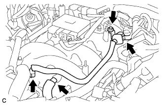
INSTALL WATER BY-PASS PIPE SUB-ASSEMBLY
-
Install the water by-pass pipe to the intake air surge tank assembly with the 2 bolts.
- Torque:
- 10 N*m { 102 kgf*cm, 7 ft.*lbf }
-
Connect the heater inlet water hose, heater outlet water hose, water inlet hose, water outlet hose, and water by-pass hose to the water by-pass pipe sub-assembly with the 5 clamps.
-
-
INSTALL NO. 1 VACUUM SWITCHING VALVE ASSEMBLY
-
Connect the ventilation hose.
-
Install the No. 1 vacuum switching valve assembly with the bolt.
- Torque:
- 21 N*m { 214 kgf*cm, 16 ft.*lbf }
-
Connect the No. 2 fuel vapor feed hose to the No. 1 vacuum switching valve assembly.
-
Connect the fuel vapor feed hose to the intake air surge tank assembly.
-
-
CONNECT ENGINE WIRE
-
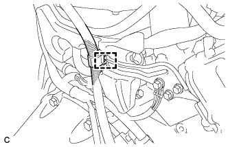
Connect the harness clamp then install the engine wire.
-
-
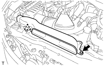
INSTALL AIR CLEANER CASE SUB-ASSEMBLY
-
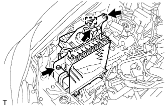
Install the air cleaner case sub-assembly with the 2 bolts.
- Torque:
- 5.0 N*m { 51 kgf*cm, 44 in.*lbf }
-
Connect the vacuum switching valve connector and clamp.
-
Connect the vacuum hose and 2 clamps.
-
-
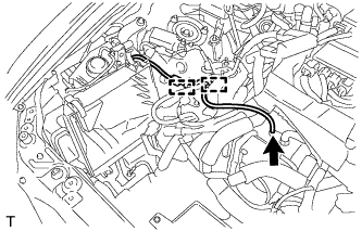
INSTALL AIR CLEANER CAP SUB-ASSEMBLY
-
Install the air cleaner cap sub-assembly with air cleaner hose and lock the 2 clamps.
Tech Tips
Tightening torque for the hose clamp located between the air cleaner cap sub-assembly and air cleaner hose assembly is as follows.
- Torque:
- 4.0 N*m { 41 kgf*cm, 35 in.*lbf }
-
Connect the air cleaner hose to the throttle body with the hose clamp.
- Torque:
- 4.0 N*m { 41 kgf*cm, 35 in.*lbf }
-
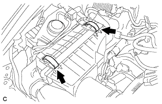
Connect the 2 ventilation hoses with the 2 hose clamps.
-
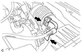
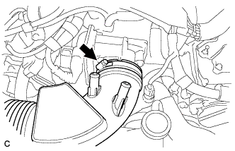
Connect the mass air flow meter connector and wire harness clamp.
-
-
INSTALL NO. 1 AIR CLEANER INLET
-
Install the No. 1 air cleaner inlet with the bolt and clip.
- Torque:
- 5.0 N*m { 51 kgf*cm, 44 in.*lbf }
-
-
CONNECT CABLE TO NEGATIVE BATTERY TERMINAL
Note
When disconnecting the cable, some systems need to be initialized after the cable is reconnected Click here.
-
ADD ENGINE COOLANT
Note
Before adding coolant, turn the A/C switch OFF.
Total capacity 11.9 liters (12.6 US qts, 10.5 Imp. qts)
-
Tighten the radiator drain cock plug by hand.
-
Tighten the 2 cylinder block drain cock plugs.
- Torque:
- 13 N*m { 133 kgf*cm, 10 ft.*lbf }
-
Add TOYOTA Super Long Life Coolant (SLLC) into the radiator reservoir.
Capacity Approximately 5.0 liters (5.3 US qts, 4.4 Imp. qts) Tech Tips
-
LEXUS vehicles are filled with TOYOTA SLLC at the factory. In order to avoid damage to the engine cooling system and other technical problems, only use TOYOTA SLLC or similar high quality ethylene glycol based non-silicate, non-amine, non-nitrite, non-borate coolant with long-life hybrid organic acid technology (coolant with long-life hybrid organic acid technology consists of a combination of low phosphates and organic acids).
-
Contact any authorized LEXUS dealer or repairer or another duly qualified and equipped professional for further details.
-
Thermostat opening timing can be confirmed by squeezing the inlet radiator hose and sensing vibrations when the coolant starts to flow inside the hose.
-
-
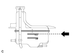
Further add coolant into the reservoir until it reaches the FULL line.
-
Squeeze the No. 1 and No. 2 radiator hoses several times, and then check the coolant level.
If the coolant level is low, add coolant.
-
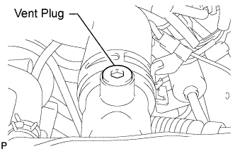
Using a 6 mm socket hexagon wrench, install the vent plug.
- Torque:
- 1.5 N*m { 15 kgf*cm, 13 in.*lbf }
-
Bleed air from the cooling system.
Note
Before starting the engine, turn the A/C switch off.
-
While idling the engine for approximately 10 minutes, make sure that the coolant remains at the FULL line by adding coolant as necessary.
-
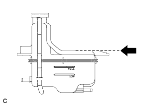
After idling the engine for 10 minutes, add coolant to the level shown in the illustration.
Capacity Approximately 2.5 to 3.5 liters (2.6 to 3.7 US qts, 2.2 to 3.1 Imp.qts) -
Close the radiator reservoir cap, and run the engine at 1500 to 2000 rpm for 5 minutes.
Tech Tips
Thermostat opening timing can be confirmed by squeezing the No. 1 radiator hose and sensing vibrations when the SLLC starts to flow inside the hose.
CAUTION:
When squeezing the radiator hose:
-
Wear protective gloves.
-
Be careful as the radiator hose is hot.
-
Keep your hands away from the radiator fan.
-
-
-
Stop the engine and wait until the coolant cools down to ambient temperature.
CAUTION:
Do not remove the radiator reservoir cap while the engine and radiator are still hot. Pressurized, hot coolant and steam may be released and cause serious burns.
-
Check the coolant level.
If the coolant level is below the FULL line, add coolant until it reaches the FULL line.
-
-
INSPECT FOR COOLANT LEAK
Note
Before performing each inspection, turn the A/C switch OFF.
CAUTION:
Do not remove the radiator reservoir cap while the engine and radiator are still hot. Pressurized, hot engine coolant and steam may be released and cause serious burns.
-
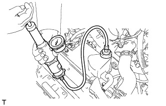
Fill the radiator with coolant and attach a radiator cap tester.
-
Warm up the engine.
-
Using the radiator cap tester, increase the pressure inside the radiator to 118 kPa (1.2 kgf/cm2, 17 psi), and check that the pressure does not drop.
If the pressure drops, check the hoses, radiator and water pump for leaks. If no external leaks are found, check the heater core, cylinder block and head.
-
-
INSPECT FOR FUEL LEAK
-
Check fuel pump operation.
-
Connect the intelligent tester to the DLC3.
-
Turn the engine switch on (IG).
Note
Do not start the engine.
-
Turn the intelligent tester on.
-
Enter the following menus: Powertrain / Engine / Active Test / Control the Fuel Pump / Speed.
-
Check for pressure in the fuel inlet tube from the fuel line. Check that sounds of fuel flowing in the fuel tank can be heard. If no sounds can be heard, check the instrument panel junction block, fuel pump, ECM and wiring connectors.
-
-
Inspect for fuel leaks.
-
Check that there are no fuel leaks from the fuel system after performing any maintenance. If there is a fuel leak, repair or replace parts as necessary.
-
-
Turn the engine switch off.
-
Disconnect the intelligent tester from the DLC3.
-
-
INSTALL ENGINE ROOM SIDE COVER LH (for LHD)
-

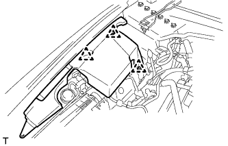
Install the engine room side cover LH with the 5 clips.
-
-
INSTALL ENGINE ROOM SIDE COVER LH (for RHD)
-
Install the engine room side cover LH with the 4 clips.
-
-
INSTALL ENGINE ROOM SIDE COVER RH (for LHD)
-
Install the engine room side cover RH with the 3 clips.
-
-
INSTALL ENGINE ROOM SIDE COVER RH (for RHD)
-
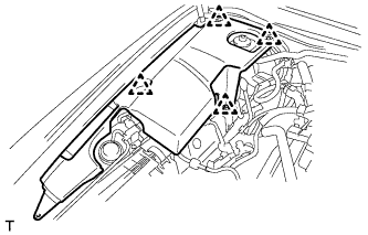
Install the engine room side cover RH with the 4 clips.
-
-
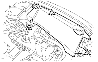
INSTALL COOL AIR INTAKE DUCT SEAL
-
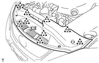
Install the cool air intake duct seal with the 9 clips.
-
-
INSTALL V-BANK COVER SUB-ASSEMBLY
-
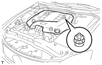
Engage the 4 clips to install the V-bank cover sub-assembly.
Note
-
Be sure to engage the clips securely.
-
Do not apply excessive force or hit the cover to engage the clips. This may cause the cover to break.
-
-
-
INSTALL ENGINE UNDER COVER