ENGINE UNIT REMOVAL

-
INSTALL ENGINE ON ENGINE STAND
-
Install the engine onto an engine stand with the bolts.
-
-
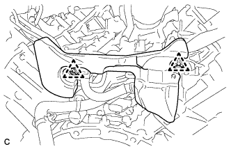
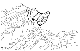
REMOVE ENGINE HANGER
-
Remove the 2 bolts and 2 engine hangers.
-
-
REMOVE ENGINE WIRE
-
Remove the engine wire.
-
-
REMOVE FRONT NO. 1 ENGINE MOUNTING BRACKET RH
-
Remove the 4 bolts and front No. 1 engine mounting bracket RH.
-
-
REMOVE FRONT NO. 1 ENGINE MOUNTING BRACKET LH
-
Remove the 4 bolts and front No. 1 engine mounting bracket LH.
-
-
REMOVE WIRE HARNESS CLAMP BRACKET
-
Remove the 2 bolts and 2 wire harness clamp brackets.
-
-
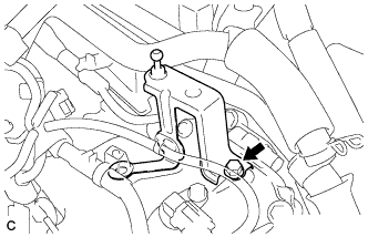
REMOVE TRANSMISSION BREATHER ASSEMBLY
-
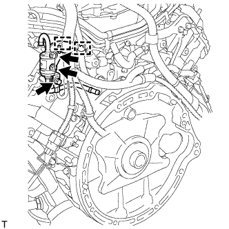
Remove the bolt and disconnect the ground wire.
-
Separate the 2 clamps and the wire harness from the transmission breather assembly.
-
Remove the 2 bolts and the transmission breather assembly.
-
-
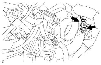
REMOVE THROTTLE BODY ASSEMBLY
-
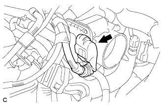
Disconnect the throttle body assembly connector.
-
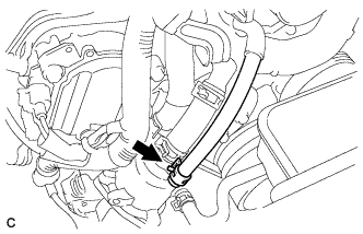
Loosen the hose clamp and separate the No. 5 water by-pass hose.
-
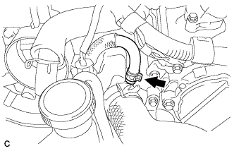
Loosen the hose clamp and separate the No. 4 water by-pass hose.
-
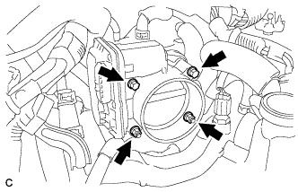
Remove the 2 bolts and 2 nuts.
-
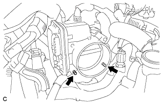
Using a "TORX" socket E6, remove the 2 stud bolts and throttle body assembly.
Note
Do not damage the water hoses when removing the throttle body assembly.
-
Remove the gasket.
-
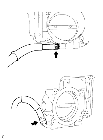
Remove the 2 water by-pass hoses from the throttle body assembly.
-
-
REMOVE INJECTOR DRIVER
-
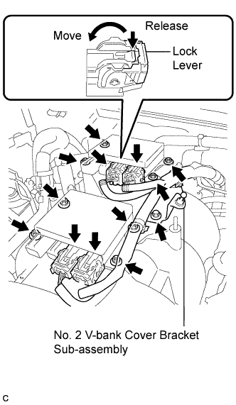
Disconnect the 4 injector driver connectors.
Tech Tips
To disconnect the injector driver connectors, push the claw downward and move the lock lever to release the lock.
-
Remove the 8 nuts and 2 injector drivers.
-
Remove the bolt and No. 2 V-bank cover bracket sub-assembly.
-
-
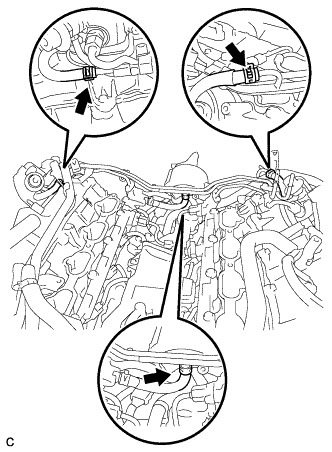
DISCONNECT WATER BY-PASS HOSE
-
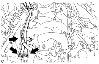
Slide the 3 clamps, and disconnect the water by-pass pipe hose, No. 3 water by-pass hose and No. 9 water by-pass hose from the water by-pass pipe sub-assembly.
-
-
DISCONNECT VENTILATION HOSE
-
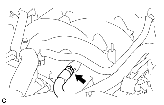
Disconnect the ventilation hose from the intake air surge tank sub assembly.
-
-
REMOVE INTAKE AIR SURGE TANK ASSEMBLY
-
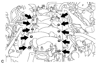
Remove the 8 bolts, 2 nuts and intake air surge tank assembly.
-
Remove the 2 gaskets from the intake air surge tank assembly.
-
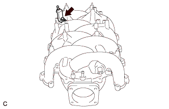
Remove the bolt and V-bank cover bracket sub-assembly.
-
Remove the bolt and union to check valve hose bracket (for LHD).
-
-
REMOVE NO. 3 COVER SUB-ASSEMBLY
-
Remove the bolt and separate the engine wire.
-
Remove the 2 bolts and bracket.
-
Remove the 2 clips and No. 3 cover sub-assembly.
-
-
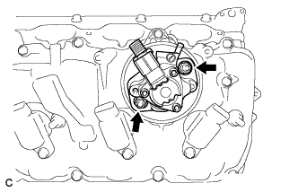
REMOVE FUEL PRESSURE PULSATION DAMPER ASSEMBLY (for Direct Injection)
-
Disconnect the harness clamp and remove the 2 bolts and brackets.
-
Disconnect the 3 fuel hoses.
-
Using SST, loosen the 2 fuel pressure pulsation damper assemblies.
- SST
- 09612-24014 ( 09617-24011 )
-
Remove the 2 clamp bolts shown in the illustration.
-
Remove the 4 gaskets and No. 1 fuel pipe sub-assembly.
-
-
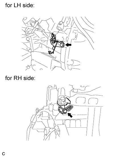
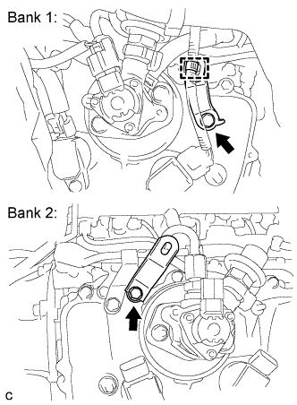
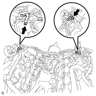
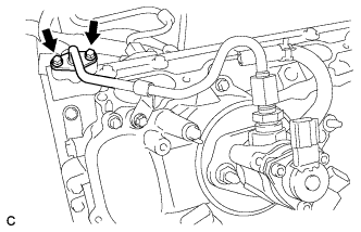
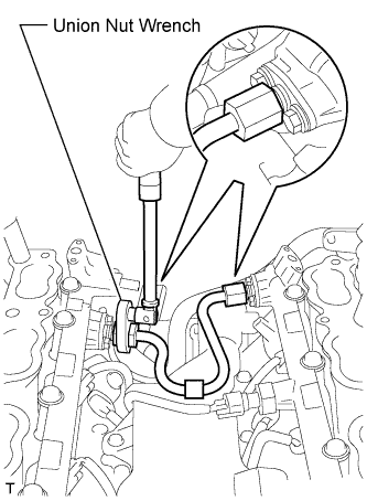
REMOVE NO. 3 FUEL PIPE SUB-ASSEMBLY
-
Remove the high pressure side fuel pump assembly connector.
-
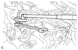
Secure the union bolt on the fuel pump assembly side in place with a 21 mm wrench. Using a 19 mm union nut wrench, loosen the union nut and disconnect the fuel pipe from the fuel pump assembly.
Note
Do not loosen the union bolt on the fuel pump side. If the union bolt is accidentally loosened, replace the fuel pump assembly.
-
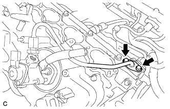
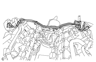
Remove the 2 bolts on the delivery pipe side and remove the No. 3 fuel pipe sub-assembly.
-
-
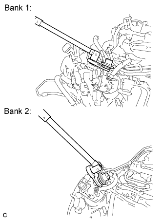
REMOVE NO. 2 FUEL PIPE SUB-ASSEMBLY
-
Remove the high pressure side fuel pump assembly connector.
-
Secure the union bolt on the fuel pump assembly side in place with a 21 mm wrench. Using a 19 mm union nut wrench, loosen the union nut and disconnect the fuel pipe from the fuel pump assembly.
Note
Do not loosen the union bolt on the fuel pump side. If the union bolt is accidentally loosened, replace the fuel pump assembly.
Tech Tips
Use the same procedure as for the bank 1 side.
-
Remove the 2 bolts on the delivery pipe side and separate the No. 2 fuel pipe sub-assembly.
-
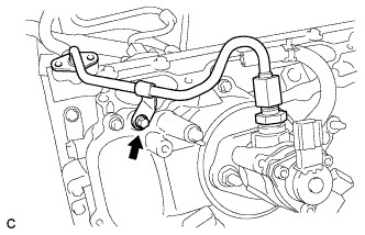
Remove the bolt and No. 2 fuel pipe sub-assembly.
-
-
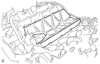
REMOVE ENGINE COVER SUB-ASSEMBLY (for Bank 1)
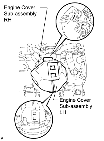
-
Detach the 5 claws and remove the engine cover sub-assembly LH and RH from the fuel pump assembly.
-
-
REMOVE ENGINE COVER SUB-ASSEMBLY (for Bank 2)
Tech Tips
Use the same procedure as for the bank 1 side.
-
REMOVE FUEL PUMP ASSEMBLY (for Bank 1)
-
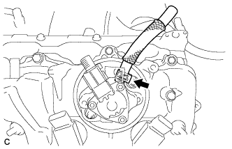
Disconnect the fuel hose from the fuel pump assembly.
-
Remove the 2 nuts, fuel pump assembly and fuel pump insulator.
-
-
REMOVE FUEL PUMP ASSEMBLY (for Bank 2)
Tech Tips
Use the same procedure as for the bank 1 side.
-
REMOVE FUEL PUMP SPACER
-
Remove the 2 fuel pimp spacers.
-
-
REMOVE NO. 1 ENGINE COVER SUB-ASSEMBLY
-
Remove the No. 1 engine cover sub-assembly.
-
-
REMOVE NO. 2 ENGINE COVER SUB-ASSEMBLY LH
-
Remove the No. 2 engine cover sub-assembly LH.
-
-
REMOVE NO. 4 FUEL PIPE SUB-ASSEMBLY
-
Using a 19 mm union nut wrench, remove the No. 4 fuel pipe sub-assembly.
-
-
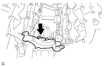
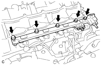
REMOVE SEPARATOR CASE
-
Disconnect the fuel pressure sensor connector.
-
Remove the 4 bolts and separator case from the cylinder head.
-
-
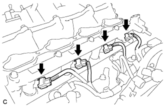
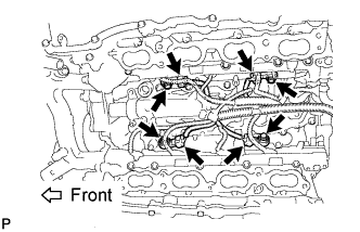
REMOVE NO. 2 FUEL DELIVERY PIPE (for Direct Injection)
-
Disconnect the 4 injector connectors.
-
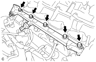
Remove the 5 bolts and the No. 2 fuel delivery pipe from the cylinder head.
Note
-
Be extremely careful not to touch or strike the tips of the injectors.
-
Pull the No. 2 fuel delivery pipe straight without tilting it.
-
-
Remove the 4 injector vibration insulators from the cylinder head.
-
-
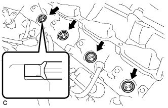
REMOVE FUEL DELIVERY PIPE (for Direct Injection)
-
Disconnect the 4 injector connectors.
-
Remove the 5 bolts and the fuel delivery pipe from the cylinder head.
Note
-
Be extremely careful not to touch or strike the tips of the injectors.
-
Pull the fuel delivery pipe straight without tilting it.
-
-
Remove the 4 injector vibration insulators from the cylinder head.
-
-
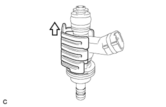
REMOVE FUEL INJECTOR ASSEMBLY (for Direct Injection)
-
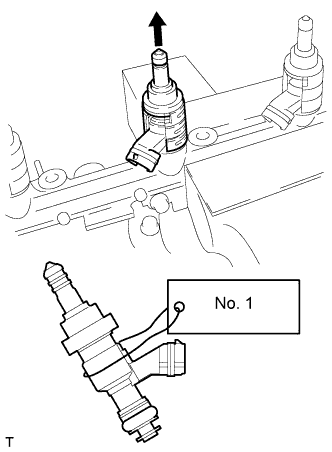
Secure the delivery pipe between aluminum plates in a vise and pull the fuel injector assembly out in a straight line.
Note
-
Pull the fuel injector assembly straight out to avoid damage to the seal surface of the fuel delivery pipe and No.2 fuel delivery pipe O-ring.
-
For reinstallation, attach a tag or label to the injector shaft.
-
-
Remove the nozzle holder clamp from the injector assembly.
-
Remove the O-ring, backup rings (No. 1, No. 2 and No. 3) and E-ring from the fuel injector.
-
-
REMOVE FUEL INJECTOR SEAL (for Direct Injection)
-
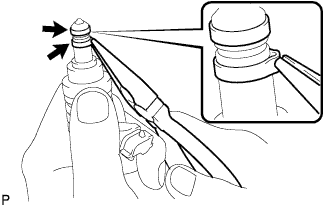
Using the tips of needle-nose pliers, pinch and pull one of the 2 fuel injector seals at several points to stretch it. Repeat this for the other fuel injector seal.
Note
-
Excessively pinching the fuel injector seal may damage the groove of the fuel injector assembly.
-
If an fuel injector assembly is dropped or the tip of an fuel injector assembly is struck, replace it with a new one.
-
-
Remove the 2 fuel injector seals from the fuel injector assembly.
-
-
REMOVE NO. 5 ENGINE WIRE
-
Disconnect the 4 knock sensor connectors.
-
Remove the 2 bolts and No. 5 engine wire.
-
-
REMOVE NO. 4 ENGINE COVER SUB-ASSEMBLY
-
Remove the engine cover.
-
-
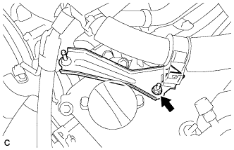
REMOVE NO. 2 IDLER PULLEY SUB-ASSEMBLY
-
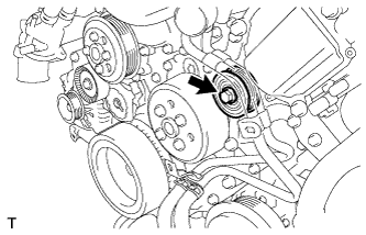
Remove the bolt and idler pulley sub-assembly.
-
-
REMOVE OIL PUMP DRIVE SHAFT PULLEY
-
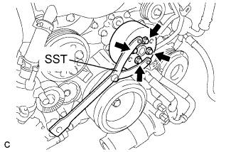
Using SST, hold the oil pump drive shaft pulley.
- SST
- 09960-10010 ( 09962-01000, 09963-00600 )
-
Remove the 4 bolts and oil pump drive shaft pulley.
-
-
REMOVE WATER PUMP PULLEY
-
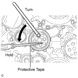
Using a screwdriver or an equivalent, hold the water pump pulley.
Tech Tips
Tape the screwdriver tip before use to avoid damage.
-
Remove the 4 bolts and water pump pulley.
-
-
REMOVE INLET WATER HOUSING
-
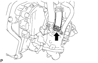
Remove the hose clamp and disconnect the water inlet hose.
-
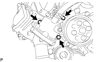
Remove the 3 bolts, inlet water housing and gasket.
-
-
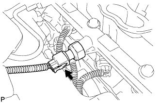
REMOVE ENGINE OIL PRESSURE SWITCH ASSEMBLY
-
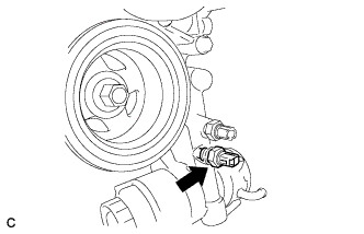
Using a deep socket wrench (24 mm) remove the engine oil pressure switch assembly.
-
-
REMOVE OIL TEMPERATURE SENSOR
-
Disconnect the temperature sensor connector.
-
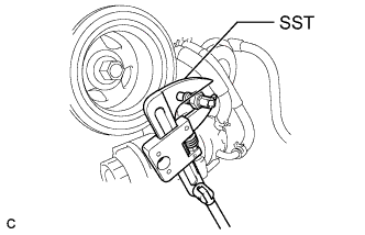
Using SST, remove the temperature sensor and gasket.
- SST
- 09922-10010
Note
-
Do not subject the oil temperature sensor to any impacts.
-
If the sensor is subjected to an impact, replace the oil temperature sensor with a new one.
-
-
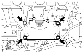
REMOVE ENGINE OIL LEVEL SENSOR
-
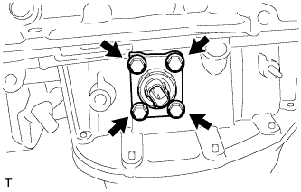
Disconnect the engine oil level sensor connector.
-
Remove the 4 bolts.
-
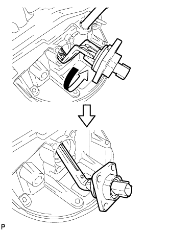
Rotate the engine oil level sensor 180° counterclockwise and remove it.
-
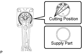
Cut off the gasket as shown in the illustration.
-
Remove the gasket from the oil level sensor.
Tech Tips
After cutting away the parts of the gasket shown in the illustration, remove only the outer part of the gasket.
-
-
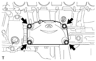
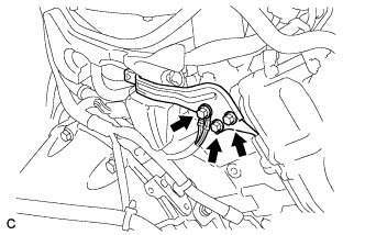
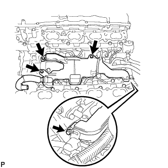
REMOVE NO. 2 WATER BY-PASS PIPE SUB-ASSEMBLY
-
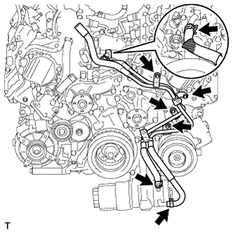
Remove the 3 hose clamps and disconnect the 3 water by-pass hoses.
-
Remove the 4 bolts and No. 2 water by-pass pipe sub-assembly.
-
-
REMOVE E.F.I. ENGINE COOLANT TEMPERATURE SENSOR
-
Disconnect the E.F.I. engine coolant temperature sensor connector.
-
Remove the E.F.I. engine coolant temperature sensor.
-
Remove the gasket from the E.F.I engine coolant temperature sensor.
-
-
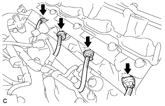
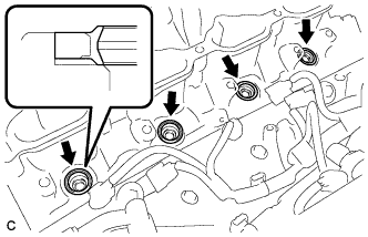
REMOVE KNOCK SENSOR
-
Disconnect the 4 knock control sensor connectors.
-
Remove the 4 bolts and 4 knock control sensors.
-
-
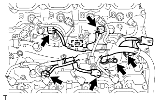
REMOVE IGNITION COIL ASSEMBLY
-
Disconnect the 8 ignition coil connectors.
-
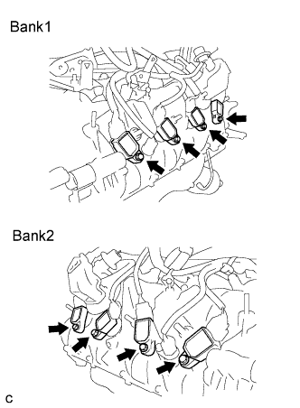
Remove the 8 bolts and 8 ignition coil assemblies.
Note
Do not damage the ignition coil assemblies when removing them.
-
-
REMOVE NO. 4 V-BANK COVER BRACKET SUB-ASSEMBLY
-
Remove the nut and No. 4 V-bank cover bracket.
-
-
REMOVE NO. 3 V-BANK COVER BRACKET SUB-ASSEMBLY
-
Remove the bolt and No. 3 V-bank cover bracket.
-