ENGINE ASSEMBLY INSTALLATION

-
INSTALL FRONT ENGINE MOUNTING INSULATOR
-
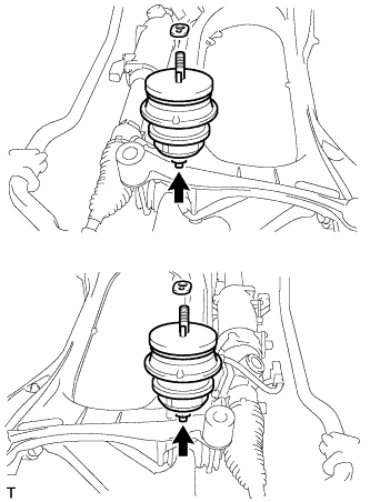
Install the 2 engine mounting insulators with the 2 nuts.
- Torque:
- 70 N*m { 714 kgf*cm, 52 ft.*lbf }
-
Install the 2 engine mounting spacers.
-
-
INSTALL FRONT SUSPENSION CROSSMEMBER SUB-ASSEMBLY
-
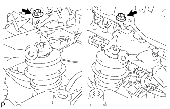
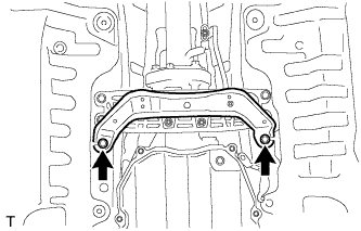
Install the front suspension crossmember sub-assembly with the 2 nuts.
- Torque:
- 35 N*m { 357 kgf*cm, 26 ft.*lbf }
-
-
INSTALL DRIVE PLATE AND RING GEAR SUB-ASSEMBLY
-
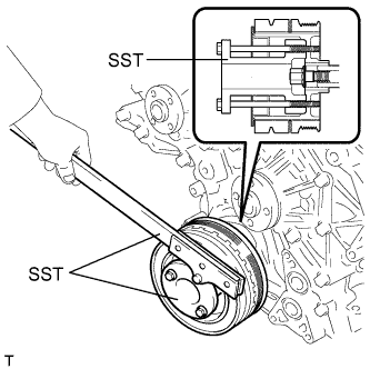
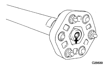
Using SST, hold the crankshaft.
- SST
- 09213-38010
- 09330-00021
-
Clean the 10 bolt holes.
-
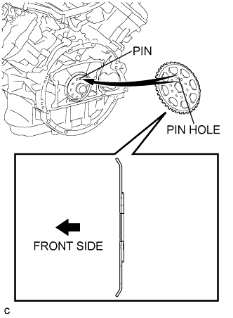
Install the crankshaft angle sensor rotor.
Tech Tips
Align the pin hole of the crankshaft angle sensor rotor with the pin of the crankshaft.
-
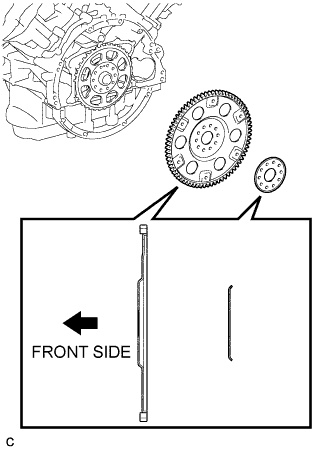
Install the drive plate and ring gear sub-assembly and drive plate spacer RR on to the crankshaft.
-
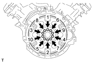
Uniformly install and tighten 10 new bolts in the sequence shown in the illustration.
- Torque:
- 30 N*m { 301 kgf*cm, 22 ft.*lbf }
Note
-
Do not reuse the drive plate and ring gear sub-assembly installation bolts.
-
Do not impact or damage the drive plate and ring gear sub-assembly installation bolts. Be sure to handle them carefully.
-
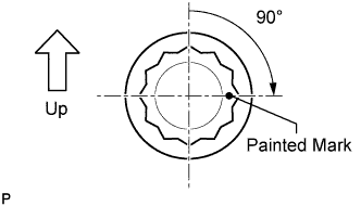
Mark the upside of each drive plate and ring gear sub-assembly installation bolt with paint.
-
Retighten the drive plate and ring gear sub-assembly installation bolts 90° as shown in the illustration.
-
Check that the painted marks are now at a 90° angle to the upside.
-
-
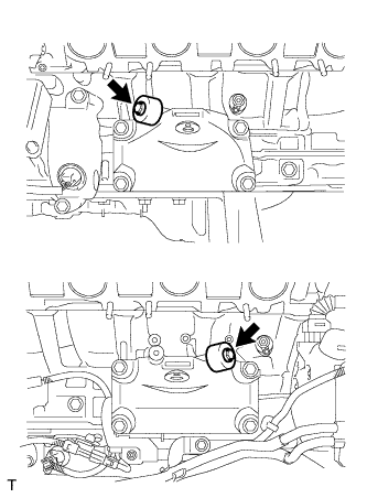
INSTALL REAR ENGINE MOUNTING INSULATOR ASSEMBLY
-
Install the rear engine mounting insulator with the 4 bolts.
- Torque:
- 30 N*m { 306 kgf*cm, 22 ft.*lbf }
-
-
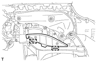
INSTALL REAR ENGINE MOUNTING MEMBER
-
Install the rear engine mounting member to the automatic transmission assembly with the 4 nuts.
- Torque:
- 13 N*m { 133 kgf*cm, 10 ft.*lbf }
-
-
INSTALL AUTOMATIC TRANSMISSION ASSEMBLY
-
Make sure that the knock pins are installed on the engine.
-
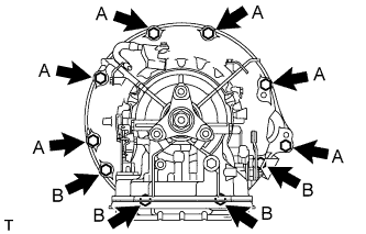
Install the automatic transmission to the engine with the 10 bolts.
- Torque:
- Bolt A
- 71 N*m { 724 kgf*cm, 52 ft.*lbf, for 17 mm bolt }
- Bolt B
- 37 N*m { 377 kgf*cm, 27 ft.*lbf, for 14 mm bolt }
Note
-
Insert dowel pins into the dowel holes securely so that the end face of the automatic transmission assembly fits close against the engine assembly before tightening the bolts.
-
Make sure that the dowel pins are not loose, bent, damaged or scratched and then install the transaxle onto the engine with the contact surfaces of the engine and transaxle flat against each other.
-
-
INSTALL DRIVE PLATE AND TORQUE CONVERTER CLUTCH SETTING BOLT
-
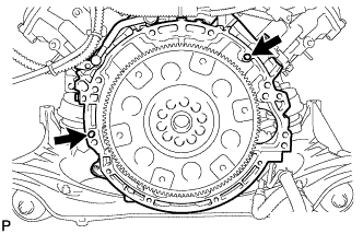
Install the 6 torque converter clutch setting bolts.
- Torque:
- 48 N*m { 489 kgf*cm, 35 ft.*lbf }
Tech Tips
First install the black colored bolt and then the remaining 5 bolts.
-
-
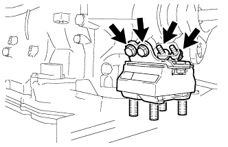
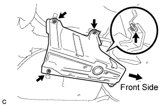
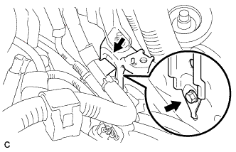
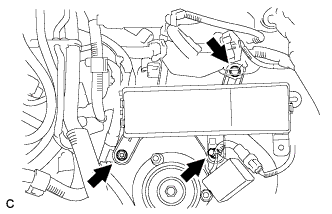
INSTALL STARTER ASSEMBLY
-
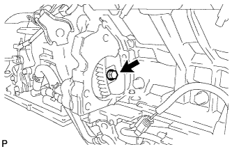
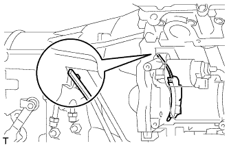
Install the flywheel housing side cover.
-
Install the terminal lower cover with the nut.
- Torque:
- 10 N*m { 102 kgf*cm, 7 ft.*lbf }
-
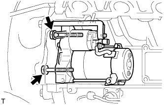
Install the starter assembly with the 2 bolts.
- Torque:
- 37 N*m { 377 kgf*cm, 27 ft.*lbf }
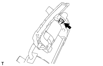
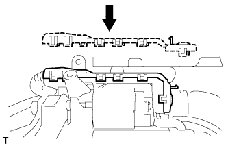
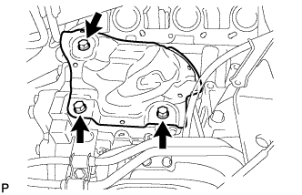
Note
Make sure that the flywheel housing side cover is as shown in the illustration.
-
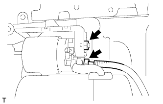
Install the wire harness with the nut.
- Torque:
- 9.8 N*m { 100 kgf*cm, 87 in.*lbf }
-
Connect the starter connector.
-
Install the terminal upper cover with the 11 claws.
-
-
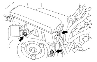
INSTALL GENERATOR ASSEMBLY
-
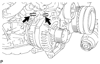
Using an E8 "TORX" socket wrench, set the generator with the 2 stud bolts.
- Torque:
- 10 N*m { 102 kgf*cm, 7 ft.*lbf }
-
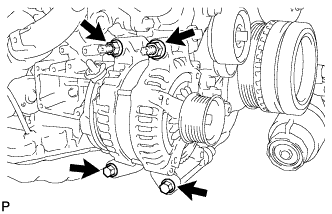
Install the generator with the 2 bolts and 2 nuts.
- Torque:
- 43 N*m { 438 kgf*cm, 32 ft.*lbf }
-
Install the wire harness bracket with the nut.
- Torque:
- 6.0 N*m { 61 kgf*cm, 53 in.*lbf }
-
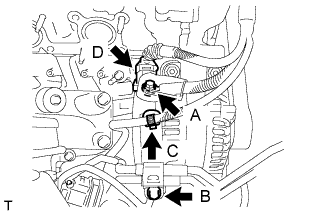
Connect the harness to the +B terminal with nut A.
- Torque:
- 12 N*m { 122 kgf*cm, 9 ft.*lbf }
-
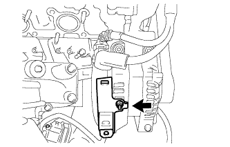
Install the oil cooler tube with bolt B.
- Torque:
- 14 N*m { 140 kgf*cm, 10 ft.*lbf }
-
Connect wire harness clamp C.
-
Connect generator connector D.
-
-
INSTALL COMPRESSOR AND PULLEY
-
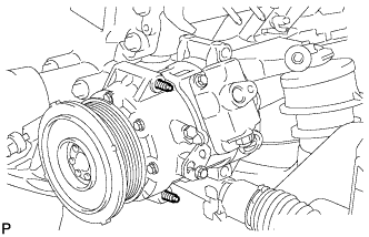
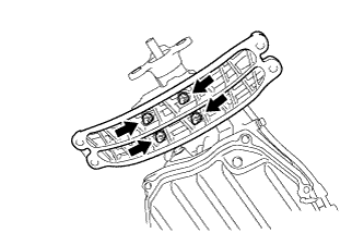
Using an E8 "TORX" socket, install the compressor and pulley with the 2 stud bolts.
- Torque:
- 10 N*m { 102 kgf*cm, 7 ft.*lbf }
-
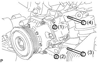
Install the compressor and pulley with the 2 bolts and 2 nuts.
- Torque:
- 25 N*m { 255 kgf*cm, 18 ft.*lbf }
Tech Tips
Tighten the bolts and nuts in the order shown in the illustration to install the compressor and pulley.
-
-
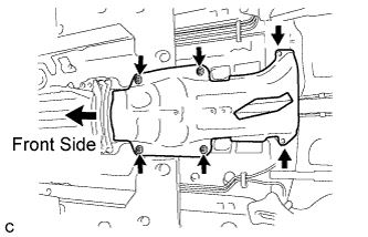
INSTALL OIL COOLER TUBE
-
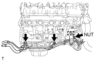
Install the oil cooler tube with the 2 bolts and nut.
- Torque:
- Bolt
- 14 N*m { 140 kgf*cm, 10 ft.*lbf }
- Nut
- 5.5 N*m { 56 kgf*cm, 49 in.*lbf }
-
Connect the wire harness clamp.
-
-
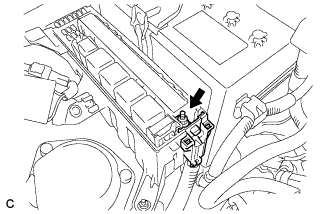
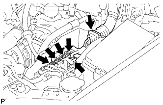
CONNECT WIRE HARNESS AND CONNECTORS
-
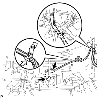
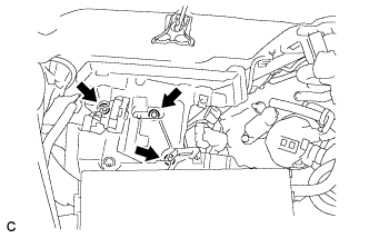
Install the nut and 2 wire harness clamps.
- Torque:
- 10 N*m { 102 kgf*cm, 7 ft.*lbf }
-
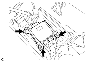
Connect the park/neutral position switch connector.
-
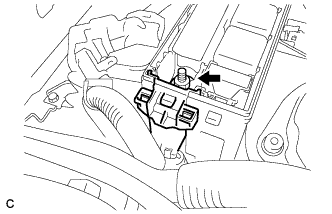
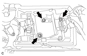
Install the 2 bolts and wire harness clamp.
- Torque:
- 10 N*m { 102 kgf*cm, 7 ft.*lbf }
-
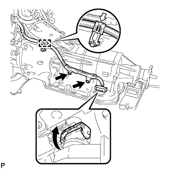
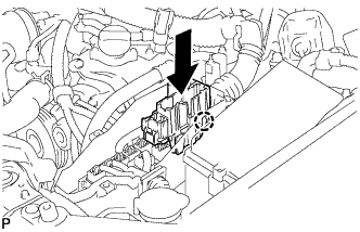
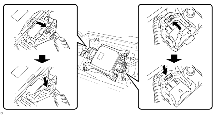
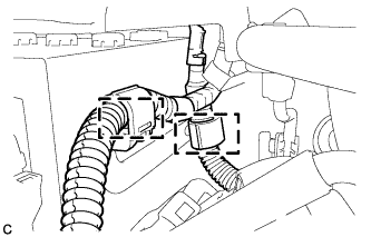
Connect the transmission wire connector.
Tech Tips
Push up the lever until the claw of the transmission wire connector makes a connection sound.
-
-
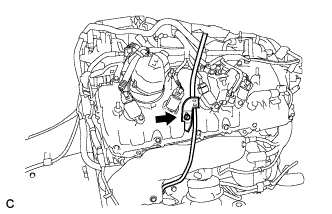
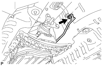
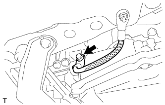
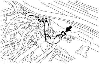
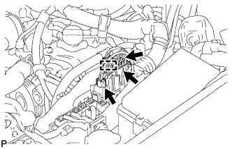
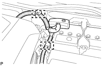
CONNECT BREATHER PLUG HOSE
-
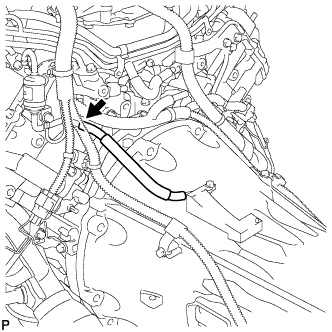
Connect the breather hose to the transmission breather assembly.
Tech Tips
Be sure to insert the breather hose until stopped by the protrusion on the transmission breather assembly.
-
-
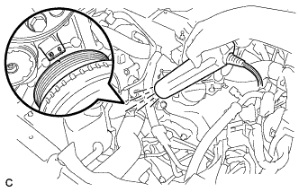
INSTALL V-RIBBED BELT
-
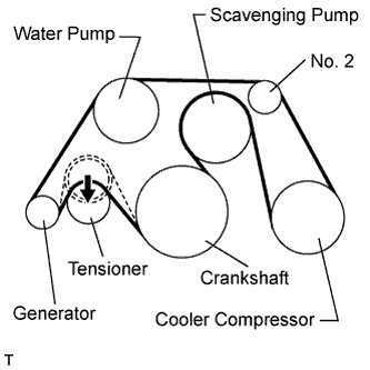
Install the V-ribbed belt as shown in the illustration.
-
Rotate the V-ribbed belt tensioner pulley counterclockwise, and then remove the bar.
Note
Check that the drive belt is properly set to each pulley.
-
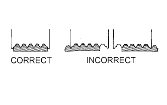
Check that the belt is properly positioned on each pulley.
-
Start the engine and check that the belt turns smoothly and no abnormal noise occurs.
-
-
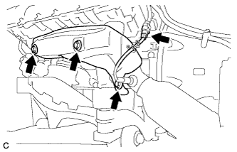
INSTALL NO. 3 EXHAUST MANIFOLD HEAT INSULATOR
-
Install the No. 3 exhaust manifold heat insulator with the 3 bolts.
- Torque:
- 10 N*m { 102 kgf*cm, 7 ft.*lbf }
-
-
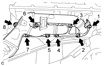
INSTALL EXHAUST MANIFOLD SUB-ASSEMBLY LH
-
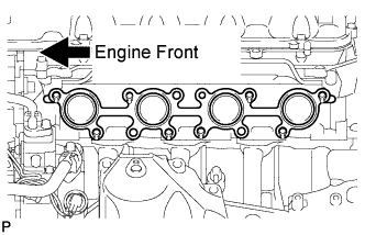
Install a new gasket.
-
Install the exhaust manifold sub-assembly LH, and install 8 new nuts in the order shown in the illustration.
- Torque:
- 21 N*m { 214 kgf*cm, 16 ft.*lbf }
-
-
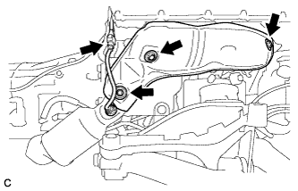
INSTALL NO. 2 EXHAUST MANIFOLD HEAT INSULATOR
-
Install the No. 2 exhaust manifold heat insulator with the 3 bolts.
- Torque:
- 10 N*m { 102 kgf*cm, 7 ft.*lbf }
-
Connect the air fuel ratio sensor connector.
-
-
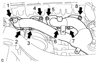
INSTALL EXHAUST MANIFOLD SUB-ASSEMBLY RH
-
Install a new gasket.
-
Install the exhaust manifold sub-assembly RH, and install 8 new nuts in the order shown in the illustration.
- Torque:
- 21 N*m { 214 kgf*cm, 16 ft.*lbf }
-
-
INSTALL NO. 1 EXHAUST MANIFOLD HEAT INSULATOR
-
Install the No. 1 exhaust manifold heat insulator with the 3 bolts.
- Torque:
- 10 N*m { 102 kgf*cm, 7 ft.*lbf }
-
Connect the air fuel ratio sensor connector.
-
-
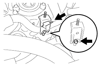
INSTALL ENGINE MOUNTING DAMPER
-
Install the 2 engine mounting dampers with the 2 bolts.
- Torque:
- 11 N*m { 112 kgf*cm, 8 ft.*lbf }
-
-
INSTALL ENGINE UNDER COVER SUB-ASSEMBLY LH
-
Install the engine under cover sub-assembly LH to the front suspension crossmember sub-assembly with the 2 clamps.
-
-
INSTALL ENGINE UNDER COVER SUB-ASSEMBLY RH
-
Install the engine under cover sub-assembly RH to the front suspension crossmember sub-assembly with the 2 clamps.
-
-
INSTALL ENGINE OIL LEVEL DIPSTICK GUIDE
-
Apply engine oil to a new O-ring, and install it to the oil level dipstick guide sub-assembly.
-
Install the oil level dipstick guide sub-assembly with the bolt.
- Torque:
- 10 N*m { 102 kgf*cm, 7 ft.*lbf }
-
-
INSTALL ENGINE OIL LEVEL DIPSTICK
-
INSTALL ENGINE AND TRANSMISSION
-
Place the engine on an engine lifter.
Tech Tips
Place the engine on wooden blocks or equivalent so that the engine is level.
-
Remove the 2 bolts and 2 No. 1 engine hangers.
-
Operate the engine lifter to install the engine into the vehicle.
Note
Make sure that the engine is clear of all wiring and hoses.
-
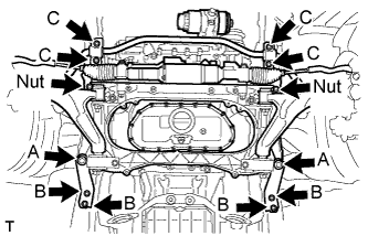
Install the 10 bolts and 2 nuts.
- Torque:
- Bolt A
- 188 N*m { 1917 kgf*cm, 138 ft.*lbf }
- Bolt B
- 50 N*m { 510 kgf*cm, 37 ft.*lbf }
- Bolt C
- 49 N*m { 500 kgf*cm, 36 ft.*lbf }
- Nut
- 154 N*m { 1570 kgf*cm, 113 ft.*lbf }
-
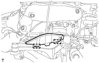
Install the rear engine mounting member to the body with the 4 bolts.
- Torque:
- 26 N*m { 260 kgf*cm, 19 ft.*lbf }
-
-
CONNECT FLOOR SHIFT GEAR SHIFTING ROD SUB-ASSEMBLY
-
Temporarily tighten the floor shift gear shifting rod sub-assembly with the nut.
-
-
INSTALL STEERING COLUMN ASSEMBLY
-
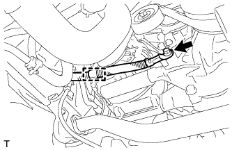
CONNECT STEERING SLIDING YOKE SUB-ASSEMBLY
-
Align the matchmarks on the steering sliding yoke sub-assembly and the power steering link assembly.
-
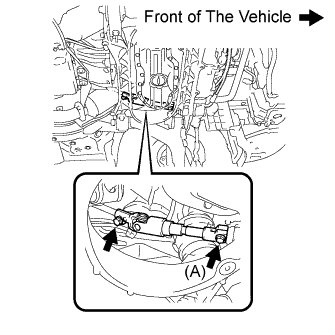
Install the bolt (A) and tighten the 2 bolts.
- Torque:
- 35 N*m { 360 kgf*cm, 26 ft.*lbf }
-
-
CONNECT HEIGHT CONTROL SENSOR LINK SUB-ASSEMBLY
-
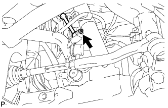
Install the front height control sensor link assembly to the front stabilizer bar assembly with the nut.
- Torque:
- 5.4 N*m { 55 kgf*cm, 48 in.*lbf }
-
-
CONNECT STEERING KNUCKLE LH
-
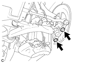
Install the steering knuckle with axle assembly to the front lower ball joint assembly with the 2 bolts.
- Torque:
- 120 N*m { 1223 kgf*cm, 89 ft.*lbf }
-
-
CONNECT STEERING KNUCKLE RH
Tech Tips
Perform the same procedure for the LH side.
-
TEMPORARILY TIGHTEN FRONT SHOCK ABSORBER ASSEMBLY LH
-
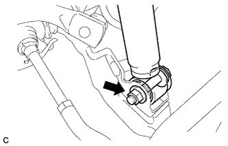
Insert the bolt from the rear of the vehicle, and install the front shock absorber lower side on the front lower suspension arm.
-
Temporarily tighten a nut while holding the bolt.
-
-
TEMPORARILY TIGHTEN FRONT SHOCK ABSORBER ASSEMBLY RH
Tech Tips
Perform the same procedure for the LH side.
-
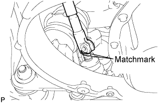
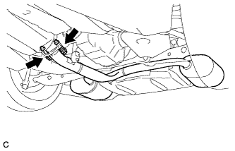
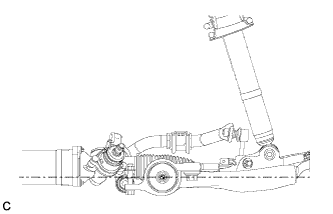
INSTALL PROPELLER SHAFT WITH CENTER BEARING ASSEMBLY
-
Apply grease to the flexible coupling centering bushings.
Grease Molybdenum disulphide lithium base NLGI No. 2 -
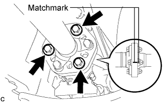
Align the matchmarks on the transmission companion flange and flexible coupling.
-
Install and tighten the 3 bolts, 3 washers and 3 nuts.
- Torque:
- 79 N*m { 805 kgf*cm, 58 ft.*lbf }
Note
Be careful not to damage the flexible coupling centering bushings.
Tech Tips
The bolts should be installed from the propeller shaft side.
-
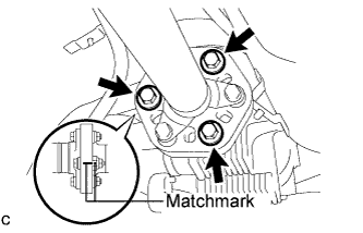
Align the matchmarks on the differential companion flange and flexible coupling.
-
Install and tighten the 3 bolts, 3 washers and 3 nuts.
- Torque:
- 79 N*m { 805 kgf*cm, 58 ft.*lbf }
Note
Be careful not to damage the flexible coupling centering bushings.
Tech Tips
The bolts should be installed from the propeller shaft side.
-
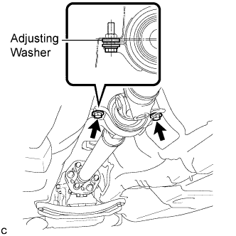
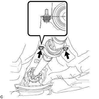
Temporarily install the 2 center support bearing set bolts with the adjusting center support bearing washers.
Tech Tips
Reuse any removed adjusting washers.
-
-
FULLY TIGHTEN NO. 1 CENTER SUPPORT BEARING ASSEMBLY
-
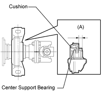
Adjust the dimension between the edge surface of the center support bearing and the edge surface of the cushion to 11.5 to 13.5 mm (0.4528 to 0.5315 in.) respectively as shown in the illustration.
(A) 11.5 to 13.5 mm (0.4528 to 0.5315 in.) -
Check that the center line of the bracket is perpendicular to the shaft axial direction.
-
Tighten the 2 bolts.
- Torque:
- 49 N*m { 500 kgf*cm, 36 ft.*lbf }
-
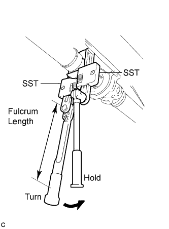
Using SST, tighten the adjusting nut.
- SST
- 09922-10010
- Torque:
- without SST
- 69 N*m { 700 kgf*cm, 51 ft.*lbf }
- with SST
- 51 N*m { 520 kgf*cm, 38 ft.*lbf }
Tech Tips
-
Use a torque wrench with a fulcrum length of 345 mm (13.6 in.).
-
Use 2 of the same SST.
-
-
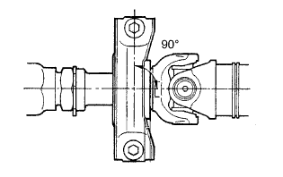
INSPECT AND ADJUST BOTH NO. 2 AND NO. 3 JOINT ANGLE
-
Stabilize the propeller shaft and differential.
-
Turn the propeller shaft several times by hand to stabilize the center support bearing.
-
-
Check both the No. 2 and No. 3 joint angles.
-
Using SST, measure the installation angle of the intermediate shaft and propeller shaft.
- SST
- 09370-50010
Tech Tips
The SST should be set directly on the bottom of the shaft.
-
Using SST, measure the installation angle of the differential.
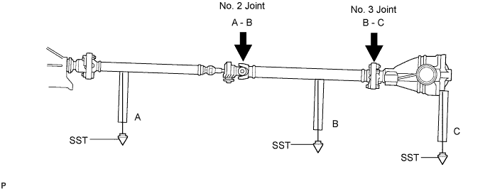
- SST
- 09370-50010
Tech Tips
Measure the installation angle by placing SST in the positions shown in the illustration.
-
Calculate the No. 2 joint angle.
No. 2 joint angle A - B = -0°19' to -1°19' A Intermediate shaft installation angle B Propeller shaft installation angle -
Calculate the No. 3 joint angle.
No. 3 joint angle B - C = 1°07' to 2°07' B Propeller shaft installation angle C Differential installation angle Tech Tips
If the measured angle is not within the specified range, adjust it with the center support bearing washers.
-
-
Adjust the No. 2 joint angle.
-
Select the center support bearing washers for adjustment.
Adjustment Washer Thickness mm (in.) 2.0 (0.0787) 4.5 (0.1772) 6.5 (0.2559) 9.0 (0.3543) 11.0 (0.4331) Note
The 2 washers should be the same thickness.
-
-
-
INSTALL OUTSIDE AIR GUIDE PLATE RH
-
Install the outside air guide plate RH with the 4 nuts.
- Torque:
- 5.4 N*m { 55 kgf*cm, 48 in.*lbf }
-
-
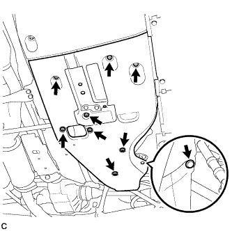
INSTALL FRONT NO. 1 FLOOR HEAT INSULATOR
-
Install the front No. 1 floor heat insulator with the 4 nuts and 2 bolts.
- Torque:
- Nut
- 5.4 N*m { 55 kgf*cm, 48 in.*lbf }
- Bolt
- 19 N*m { 194 kgf*cm, 14 ft.*lbf }
-
-
INSTALL FRONT EXHAUST PIPE ASSEMBLY
-
Install 2 new gaskets to the exhaust manifold RH and exhaust manifold LH.
-
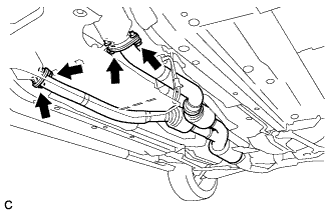
Install the front exhaust pipe assembly with 4 new bolts and 4 new nuts.
- Torque:
- 39 N*m { 398 kgf*cm, 29 ft.*lbf }
-
-
CONNECT HEATED OXYGEN SENSOR
-
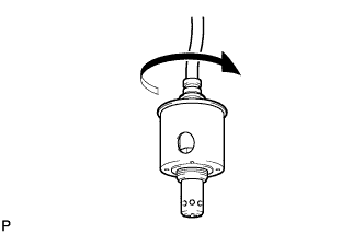
Rotate the heated oxygen sensors 4 times counterclockwise, and then install them to the front exhaust pipe assembly by hand.
-
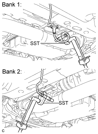
Using SST, tighten the 2 heated oxygen sensors.
- SST
- 09224-00010
- Torque:
- with SST
- 40 N*m { 408 kgf*cm, 30 ft.*lbf }
- without SST
- 44 N*m { 449 kgf*cm, 32 ft.*lbf }
Tech Tips
-
Use a torque wrench with a fulcrum length of 30 cm (11.8 in.). If the fulcrum length is not as specified, calculate the torque value based on the specification for when SST is not used Click here.
-
Make sure that SST and the wrench are connected in a straight line.
-
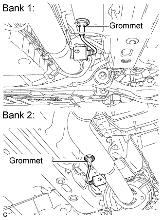
Connect the 2 grommets to the floor panel.
-
-
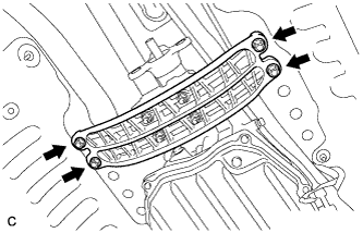
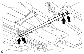
INSTALL FRONT CENTER FLOOR BRACE
-
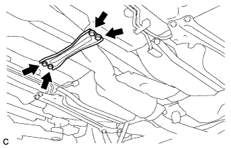
Install the front center floor brace with the 4 bolts.
- Torque:
- 7.4 N*m { 76 kgf*cm, 66 in.*lbf }
-
-
INSTALL REAR NO. 1 FLOOR PANEL BRACE
-
Install the rear No. 1 floor panel brace with the 4 bolts.
- Torque:
- 19 N*m { 194 kgf*cm, 14 ft.*lbf }
-
-
INSTALL TAIL EXHAUST PIPE ASSEMBLY
-
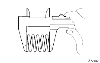
Using a vernier caliper, measure the free length of the compression springs.
Minimum length 41.5 mm (1.634 in.) If the free length is less than the minimum, replace the compression spring.
-
Fully insert a new gasket to the front exhaust pipe assembly.
-
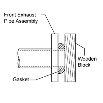
Using a plastic hammer and wooden block, tap in the new gasket until its surface is flush with the front exhaust pipe assembly.
Note
-
Be sure to install the gasket in the correct direction.
-
Do not reuse the gasket.
-
Do not damage the gasket.
-
Do not push in the gasket by using the exhaust pipe when connecting it.
-
-
Connect the tail exhaust pipe assembly to the 6 exhaust pipe supports.
-
Install the tail exhaust pipe assembly with the 2 bolts and 2 compression springs.
- Torque:
- 43 N*m { 440 kgf*cm, 32 ft.*lbf }
-
-
INSTALL NO. 2 FLOOR UNDER COVER
-
Install the No. 2 floor under cover with the 6 clips and 3 grommets.
-
-
INSTALL NO. 1 FLOOR UNDER COVER
-
Install the No. 1 floor under cover with the 5 clips and 3 grommets.
-
-
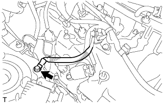
CONNECT WIRE HARNESS
-
Install the ground cable with the nut.
- Torque:
- 10 N*m { 102 kgf*cm, 7 ft.*lbf }
-
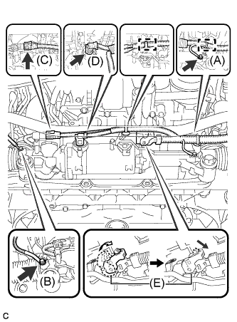
Connect the power steering wire harness. (for LHD)
-
Connect wire harness connector (D) to the power steering link assembly and securely lock the connector.
-
Connect 2 wire harness connectors (B) and (C) to the power steering link assembly.
-
Install the 2 wire harness clamps to the power steering link assembly.
-
Connect the earth wire to the bracket with bolt (A).
- Torque:
- 8.0 N*m { 82 kgf*cm, 71 in.*lbf }
-
-
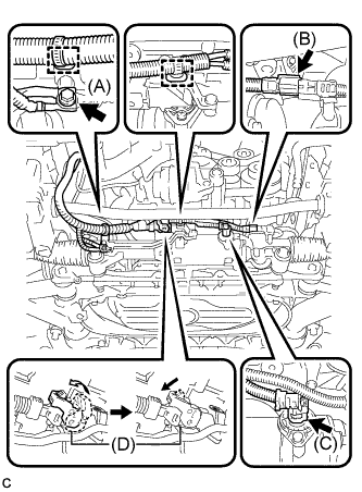
Connect the power steering wire harness. (for RHD)
-
Connect wire harness connector (E) to the power steering link assembly and securely lock the connector.
-
Connect 2 wire harness connectors (C) and (D) to the power steering link assembly.
-
Install the 2 wire harness clamps to the power steering link assembly.
-
Connect the earth wire to the bracket with bolt (A).
- Torque:
- Bolt (A)
- 13 N*m { 133 kgf*cm, 9 ft.*lbf }
- Bolt (B)
- 5.0 N*m { 51 kgf*cm, 44 in.*lbf }
-
-
Connect the ground cable with the bolt and clamp.
- Torque:
- 21 N*m { 214 kgf*cm, 15 ft.*lbf }
-
Connect the ground cable with the bolt.
- Torque:
- 8.0 N*m { 82 kgf*cm, 71 in.*lbf }
-
Connect the wire to the engine room No. 1 junction block. (for LHD)
-
Connect the clamp. (for LHD)
-
Connect the wire to the engine room No. 1 junction block. (for RHD)
-
Connect the clamp. (for RHD)
-
Install the nut and connect the wire harness. (for LHD)
- Torque:
- 12 N*m { 122 kgf*cm, 9 ft.*lbf }
-
Install the nut and connect the wire harness. (for RHD)
- Torque:
- 12 N*m { 122 kgf*cm, 9 ft.*lbf }
-
Install the No. 1 engine room relay block cover.
-
Connect the positive (+) battery cable with the nut and clamp. (for LHD)
- Torque:
- 13 N*m { 130 kgf*cm, 9 ft.*lbf }
-
Connect the positive (+) battery cable with the nut and clamp. (for RHD)
- Torque:
- 13 N*m { 130 kgf*cm, 9 ft.*lbf }
-
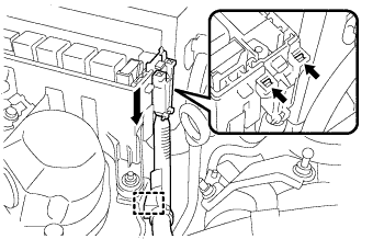
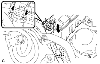
Connect the 5 connectors and grommet to the ECM box.
-
Connect the No. 4 connector holder.
-
Connect the 3 connectors and connector clamp.
-
-
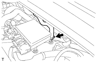
INSTALL ENGINE ROOM ECU COVER
-
Install the engine room ECU cover with 3 bolts.
- Torque:
- 5.5 N*m { 56 kgf*cm, 49 in.*lbf }
-
-
INSTALL WIRE HARNESS CLAMP BRACKET (for LHD)
-
Install the wire harness clamp bracket with the bolt.
- Torque:
- 8.0 N*m { 82 kgf*cm, 71 in.*lbf }
-
Install the wire harness clamp to the clamp bracket.
-
Install the No. 7 engine room relay block with the 2 bolts and nut.
- Torque:
- 8.0 N*m { 82 kgf*cm, 71 in.*lbf }
-
-
INSTALL WIRE HARNESS CLAMP BRACKET (for RHD)
-
Install the wire harness clamp bracket with the bolt.
- Torque:
- 8.0 N*m { 82 kgf*cm, 71 in.*lbf }
-
Install the wire harness clamp to the clamp bracket.
-
Install the No. 7 engine room relay block with the 2 bolts and nut.
- Torque:
- 8.0 N*m { 82 kgf*cm, 71 in.*lbf }
-
-
INSTALL BATTERY TRAY (for LHD)
-
Install the battery tray with the 3 bolts.
- Torque:
- 5.4 N*m { 55 kgf*cm, 48 in.*lbf }
-
-
INSTALL BATTERY TRAY (for RHD)
-
Install the battery tray with the 3 bolts.
- Torque:
- 5.4 N*m { 55 kgf*cm, 48 in.*lbf }
-
-
INSTALL POWER STEERING ECU ASSEMBLY
-
Install the power steering ECU assembly to the battery tray with the 3 bolts.
- Torque:
- 7.5 N*m { 76 kgf*cm, 66 in.*lbf }
-
Connect the connectors (A), (B) and (C) to the power steering ECU assembly.
-
Securely lock the connectors (A) and (B).
-
-
INSTALL NO. 1 BATTERY TRAY SUPPORT
-
INSTALL BATTERY (for LHD)
-
Install the battery.
-
Install the battery insulator.
-
Install the battery clamp with a nut.
- Torque:
- 2.9 N*m { 30 kgf*cm, 26 in.*lbf }
-
Connect the cable to the positive (+) battery terminal.
- Torque:
- 5.4 N*m { 55 kgf*cm, 48 in.*lbf }
-
Connect the 2 clamps.
-
-
INSTALL BATTERY (for RHD)
-
Install the battery.
-
Install the battery insulator.
-
Install the battery clamp with a nut.
- Torque:
- 2.9 N*m { 30 kgf*cm, 26 in.*lbf }
-
Connect the cable to the positive (+) battery terminal.
- Torque:
- 5.4 N*m { 55 kgf*cm, 48 in.*lbf }
-
Connect the 2 clamps.
-
-
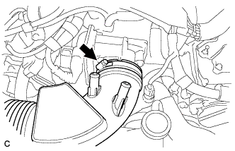
INSTALL DISCHARGE HOSE SUB-ASSEMBLY
-
Remove the vinyl tape attached to the hose.
-
Apply sufficient compressor oil to a new O-ring and the fitting surface of the compressor and pulley.
Compressor oil ND-OIL 8 or equivalent -
Install the O-ring onto the discharge hose sub-assembly.
-
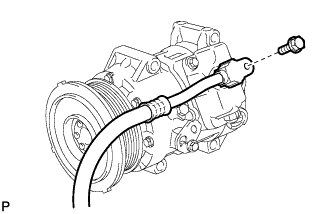
Install the discharge hose sub-assembly onto the compressor and pulley with the bolt.
- Torque:
- 9.8 N*m { 100 kgf*cm, 87 in.*lbf }
-
-
INSTALL NO. 1 COOLER REFRIGERANT SUCTION HOSE
-
Remove the vinyl tape attached to the hose.
-
Apply sufficient compressor oil to a new O-ring and the fitting surface of the compressor and pulley.
Compressor oil ND-OIL 8 or equivalent -
Install the O-ring onto the No. 1 cooler refrigerant suction hose.
-
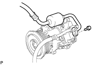
Install the No. 1 cooler refrigerant suction hose onto the compressor and pulley with the bolt.
- Torque:
- 9.8 N*m { 100 kgf*cm, 87 in.*lbf }
-
Engage each clamp.
-
Connect the connector.
-
-
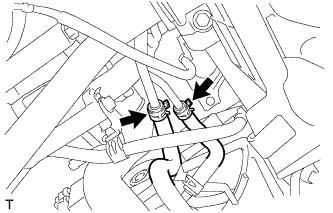
CONNECT NO. 1 FUEL HOSE
-

Push in the fuel tube connector to the No. 1 fuel hose until the fuel tube connector makes a "click" sound.
Note
-
Check that there is no damage or foreign objects on the fuel pipe connectors.
-
After connecting, check that the fuel tube connector and the pipe are securely connected by pulling on them.
-
-
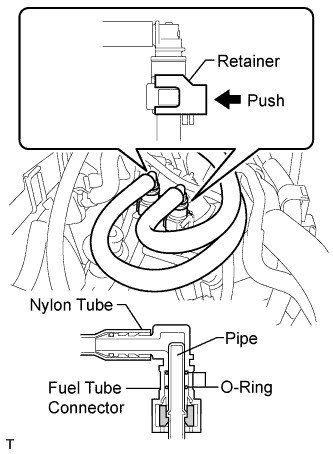
Push in the fuel tube connector to the No. 1 fuel hose until the fuel tube connector makes a "click" sound.
-
Push down on the retainer to lock it in place.
Note
-
Check that there is no damage or foreign objects on the fuel pipe connectors.
-
After connecting, check that the fuel tube connector and the pipe are securely connected by pulling on them.
-
-
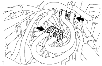
Install the 2 fuel pipe clamps.
-
-
CONNECT NO. 3 FUEL HOSE
-
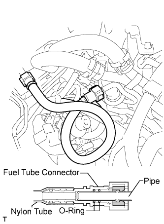
Push in the fuel tube connector to the No. 3 fuel hose until the fuel tube connector makes a "click" sound.
Note
-
Check that there is no damage or foreign objects on the fuel pipe connectors.
-
After connecting, check that the fuel tube connector and the pipe are securely connected by pulling on them.
-
-
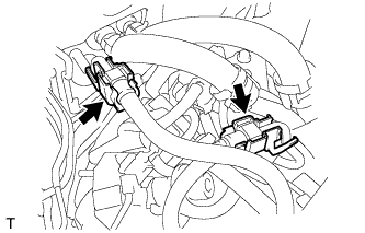
Install the 2 fuel pipe clamps.
-
-
INSTALL NO. 2 FUEL VAPOR FEED HOSE
-
Connect the No. 2 fuel vapor feed hose.
-
-
CONNECT VACUUM HOSE ASSEMBLY (for LHD)
-
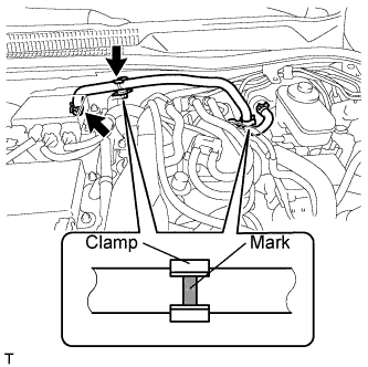
Connect the vacuum hose assembly to the intake air surge tank assembly with the clamp.
-
Connect the vacuum hose assembly to the hose clamp.
Note
Align the vacuum hose assembly matchmarks and the hose clamps as shown in the illustration.
-
-
CONNECT VACUUM HOSE ASSEMBLY (for RHD)
-
Connect the vacuum hose assembly to the intake air surge tank assembly with the clamp.
-
-
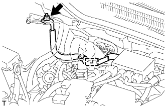
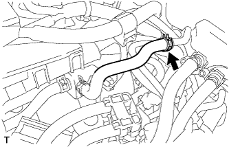
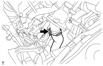
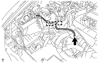
INSTALL HEATER WATER OUTLET HOSE A
-
Connect the heater water outlet hose A.
-
-
INSTALL HEATER WATER HOSE INLET A
-
Connect the heater water inlet hose A.
-
-
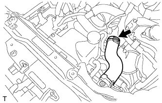
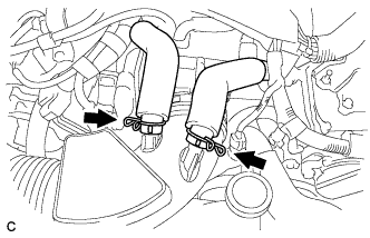
CONNECT NO. 2 OIL COOLER OUTLET HOSE
-
Connect the No. 2 oil cooler outlet hose with the clip.
-
-
CONNECT NO. 2 OIL COOLER INLET HOSE
-
Connect the No. 2 oil cooler inlet hose with the clip.
-
-
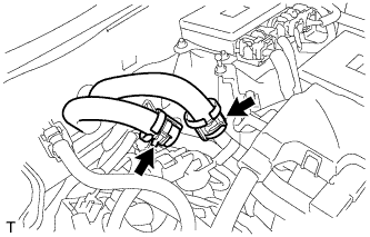
CONNECT NO. 2 RADIATOR HOSE
-
Connect the No. 2 radiator hose with the clamp.
-
-
CONNECT NO. 1 RADIATOR HOSE
-
Connect the No. 1 radiator hose with the clamp.
-
-
CONNECT RESERVE TANK OUTLET HOSE
-
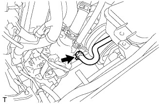
Connect the reserve tank outlet hose with the clamp.
-
-
INSTALL AIR CLEANER CASE SUB-ASSEMBLY
-
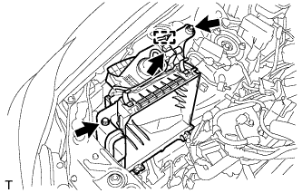
Install the air cleaner case sub-assembly with the 2 bolts.
- Torque:
- 5.0 N*m { 51 kgf*cm, 44 in.*lbf }
-
Connect the vacuum switching valve connector and clamp.
-
Connect the vacuum hose and 2 clamps.
-
-
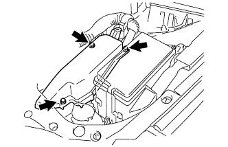
INSTALL AIR CLEANER CAP SUB-ASSEMBLY
-
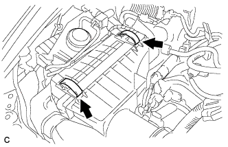
Install the air cleaner cap sub-assembly with air cleaner hose and lock the 2 clamps.
Tech Tips
Tightening torque for the hose clamp located between the air cleaner cap sub-assembly and air cleaner hose assembly is as follows.
- Torque:
- 4.0 N*m { 41 kgf*cm, 35 in.*lbf }
-
Connect the air cleaner hose to the throttle body with the hose clamp.
- Torque:
- 4.0 N*m { 41 kgf*cm, 35 in.*lbf }
-
Connect the 2 ventilation hoses with the 2 hose clamps.
-
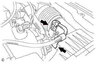
Connect the mass air flow meter connector and wire harness clamp.
-
-
CONNECT CABLE TO NEGATIVE BATTERY TERMINAL
Note
-
Make sure that the cable has been disconnected from the battery terminal for at least 2 seconds before reconnecting the cable.
-
Connect the cable to the negative (-) battery terminal with the front wheels facing straight ahead.
-
When disconnecting the cable, some systems need to be initialized after the cable is reconnected Click here.
-
Reset the auto tilt away function setting to the previous condition by changing the customize parameter Click here.
-
-
ADD ENGINE OIL
-
Add fresh oil.
Standard Engine Oil Oil Grade Oil Viscosity (SAE) API grade SM multigrade engine oil
-
5W-30
-
10W-30
(5W-30 is best choice for fuel economy and good starting in cold weather.)
Standard Capacity Item Specified Condition Drain and refill with oil filter change 9.3 liters (9.8 US qts, 8.2 Imp. qts) Drain and refill without oil filter change 8.2 liters (8.7 US qts, 7.2 Imp. qts) Dry fill 10.5 liters (11.1 US qts, 9.2 Imp. qts) -
-
Install the oil filler cap.
-
-
ADD ENGINE COOLANT
Note
Before adding coolant, turn the A/C switch OFF.
Total capacity 11.9 liters (12.6 US qts, 10.5 Imp. qts)
-
Tighten the radiator drain cock plug by hand.
-
Tighten the 2 cylinder block drain cock plugs.
- Torque:
- 13 N*m { 133 kgf*cm, 10 ft.*lbf }
-
Add TOYOTA Super Long Life Coolant (SLLC) into the radiator reservoir.
Capacity Approximately 5.0 liters (5.3 US qts, 4.4 Imp. qts) Tech Tips
-
LEXUS vehicles are filled with TOYOTA SLLC at the factory. In order to avoid damage to the engine cooling system and other technical problems, only use TOYOTA SLLC or similar high quality ethylene glycol based non-silicate, non-amine, non-nitrite, non-borate coolant with long-life hybrid organic acid technology (coolant with long-life hybrid organic acid technology consists of a combination of low phosphates and organic acids).
-
Contact any authorized LEXUS dealer or repairer or another duly qualified and equipped professional for further details.
-
Thermostat opening timing can be confirmed by squeezing the inlet radiator hose and sensing vibrations when the coolant starts to flow inside the hose.
-
-
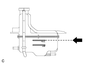
Further add coolant into the reservoir until it reaches the FULL line.
-
Squeeze the No. 1 and No. 2 radiator hoses several times, and then check the coolant level.
If the coolant level is low, add coolant.
-
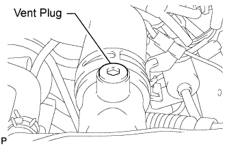
Using a 6 mm socket hexagon wrench, install the vent plug.
- Torque:
- 1.5 N*m { 15 kgf*cm, 13 in.*lbf }
-
Bleed air from the cooling system.
Note
Before starting the engine, turn the A/C switch off.
-
While idling the engine for approximately 10 minutes, make sure that the coolant remains at the FULL line by adding coolant as necessary.
-
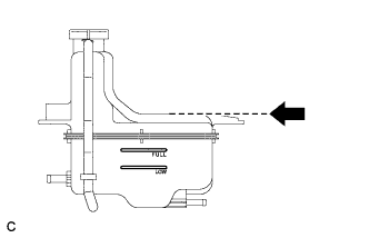
After idling the engine for 10 minutes, add coolant to the level shown in the illustration.
Capacity Approximately 2.5 to 3.5 liters (2.6 to 3.7 US qts, 2.2 to 3.1 Imp.qts) -
Close the radiator reservoir cap, and run the engine at 1500 to 2000 rpm for 5 minutes.
Tech Tips
Thermostat opening timing can be confirmed by squeezing the No. 1 radiator hose and sensing vibrations when the SLLC starts to flow inside the hose.
CAUTION:
When squeezing the radiator hose:
-
Wear protective gloves.
-
Be careful as the radiator hose is hot.
-
Keep your hands away from the radiator fan.
-
-
-
Stop the engine and wait until the coolant cools down to ambient temperature.
CAUTION:
Do not remove the radiator reservoir cap while the engine and radiator are still hot. Pressurized, hot coolant and steam may be released and cause serious burns.
-
Check the coolant level.
If the coolant level is below the FULL line, add coolant until it reaches the FULL line.
-
-
ADD AUTOMATIC TRANSMISSION FLUID
-
CHARGE REFRIGERANT
-
Perform vacuum purging using a vacuum pump.
-
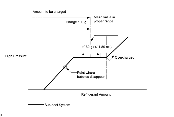
Charge refrigerant HFC-134a (R134a).
Standard 400 to 500g (14.10 to 17.63 oz.) - SST
- 09985-20010 ( 09985-02010, 09985-02050, 09985-02060, 09985-02070, 09985-02080, 09985-02090, 09985-02110, 09985-02130, 09985-02140, 09985-02150 )
Note
-
Do not operate the cooler compressor before charging refrigerant as the cooler compressor will not work properly without any refrigerant, and will overheat.
-
Approximately 100 g (3.53 oz.) of refrigerant may need to be charged after bubbles disappear. The refrigerant amount should be checked by measuring its quantity, and not with the sight glass.
-
-
INSPECT FOR OIL LEAK
-
INSPECT FOR COOLANT LEAK
Note
Before performing each inspection, turn the A/C switch OFF.
CAUTION:
Do not remove the radiator reservoir cap while the engine and radiator are still hot. Pressurized, hot engine coolant and steam may be released and cause serious burns.
-
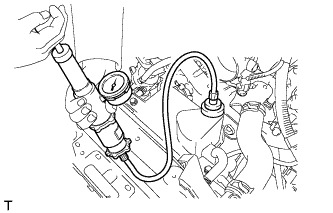
Fill the radiator with coolant and attach a radiator cap tester.
-
Warm up the engine.
-
Using the radiator cap tester, increase the pressure inside the radiator to 118 kPa (1.2 kgf/cm2, 17 psi), and check that the pressure does not drop.
If the pressure drops, check the hoses, radiator and water pump for leaks. If no external leaks are found, check the heater core, cylinder block and head.
-
-
INSPECT FOR FUEL LEAK
-
Check fuel pump operation.
-
Connect the intelligent tester to the DLC3.
-
Turn the engine switch on (IG).
Note
Do not start the engine.
-
Turn the intelligent tester on.
-
Enter the following menus: Powertrain / Engine / Active Test / Control the Fuel Pump / Speed.
-
Check for pressure in the fuel inlet tube from the fuel line. Check that sounds of fuel flowing in the fuel tank can be heard. If no sounds can be heard, check the instrument panel junction block, fuel pump, ECM and wiring connectors.
-
-
Inspect for fuel leaks.
-
Check that there are no fuel leaks from the fuel system after performing any maintenance. If there is a fuel leak, repair or replace parts as necessary.
-
-
Turn the engine switch off.
-
Disconnect the intelligent tester from the DLC3.
-
-
INSPECT FOR EXHAUST GAS LEAK
-
INSTALL FRONT WHEEL
-
STABILIZE SUSPENSION
-
Install the front wheel.
- Torque:
- 103 N*m { 1050 kgf*cm, 76 ft.*lbf }
-
Lower the vehicle and bounce it up and down several times to stabilize the front suspension. Raise the vehicle.
-
Remove the front wheel.
-
Jack up the front lower suspension arm placing a wooden block in between. Apply a load to the front suspension so that the front lower suspension arm is placed in a horizontal position.
-
-
FULLY TIGHTEN FRONT SHOCK ABSORBER ASSEMBLY LH
-
Fully tighten the bolt on the lower side of the front shock absorber while holding the nut.
- Torque:
- 157 N*m { 1601 kgf*cm, 116 ft.*lbf }
-
-
FULLY TIGHTEN FRONT SHOCK ABSORBER ASSEMBLY RH
Tech Tips
Perform the same procedure for the LH side.
-
PLACE FRONT WHEELS FACING STRAIGHT AHEAD
-
CHECK AND ADJUST FRONT WHEEL ALIGNMENT
-
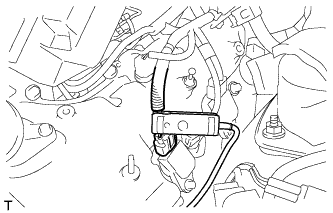
ADJUST SHIFT LEVER POSITION
-
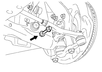
Remove the nut and disconnect the shifting rod.
-
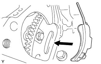
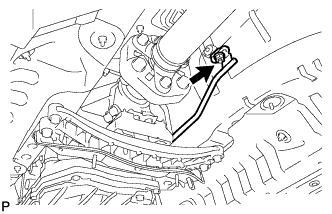
Turn the control shaft lever of the park/neutral position switch counterclockwise until it stops, and turn it clockwise 2 notches to set it to N.
-
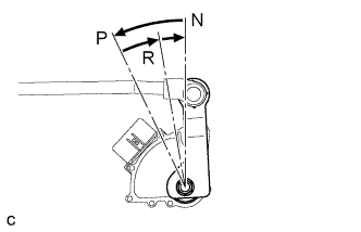
Move the shift lever to N and tighten the nut while lightly pushing the lever toward R.
- Torque:
- 13 N*m { 130 kgf*cm, 9 ft.*lbf }
Note
Do not push the shift lever too hard.
-
Check that the shift lever moves smoothly and the shift lever and gear operate correctly Click here.
-
-
INSPECT SHIFT LEVER POSITION
-
When shifting from P to R with the engine switch on (IG) and the brake pedal depressed, make sure that the shift lever moves smoothly and moves correctly into the position.
-
Check that the shift lever does not stop when moving the shift lever from R to P, and check that the shift lever does not stick when moving the shift lever from D to M.
-
Start the engine and make sure that the vehicle moves forward when shifting from N to D and moves rearward when shifting to R.
If an operation cannot be done as specified, inspect the park/neutral position switch assembly and check the shift lever assembly installation condition.
-
-
INSTALL ENGINE UNDER COVER AIR GUIDE BRACKET
-
Install the engine under cover air guide bracket with the 2 bolts.
- Torque:
- 26 N*m { 265 kgf*cm, 19 ft.*lbf }
-
-
INSTALL FRONT LOWER SUSPENSION MEMBER PROTECTOR
-
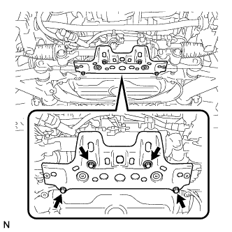
Install the front lower suspension member protector to the front suspension cross member with the 4 bolts.
- Torque:
- 8.0 N*m { 82 kgf*cm, 71 in.*lbf }
-
-
INSTALL NO. 2 ENGINE UNDER COVER
-
INSTALL REAR ENGINE UNDER COVER RH
-
INSTALL REAR ENGINE UNDER COVER LH
-
INSTALL ENGINE UNDER COVER
-
INSTALL NO. 1 AIR CLEANER INLET
-
Install the No. 1 air cleaner inlet with the bolt and clip.
- Torque:
- 5.0 N*m { 51 kgf*cm, 44 in.*lbf }
-
-
INSTALL ENGINE ROOM SIDE COVER RH (for LHD)
-
Install the engine room side cover RH with the 3 clips.
-
-
INSTALL ENGINE ROOM SIDE COVER RH (for RHD)
-
Install the engine room side cover RH with the 4 clips.
-
-
INSTALL ENGINE ROOM SIDE COVER LH (for LHD)
-

Install the engine room side cover LH with the 5 clips.
-
-
INSTALL ENGINE ROOM SIDE COVER LH (for RHD)
-
Install the engine room side cover LH with the 4 clips.
-
-
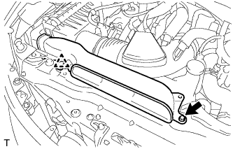
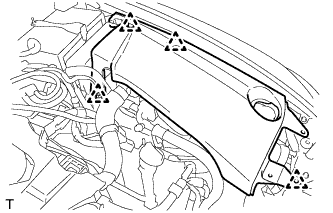
INSTALL COOL AIR INTAKE DUCT SEAL
-
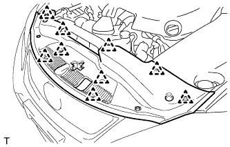
Install the cool air intake duct seal with the 9 clips.
-
-
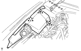
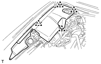
INSTALL V-BANK COVER SUB-ASSEMBLY
-
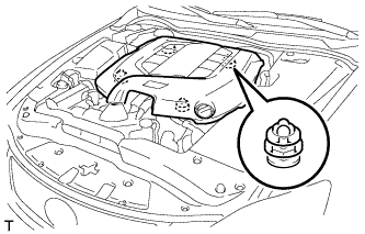
Engage the 4 clips to install the V-bank cover sub-assembly.
Note
-
Be sure to engage the clips securely.
-
Do not apply excessive force or hit the cover to engage the clips. This may cause the cover to break.
-
-
-
INSPECT IGNITION TIMING
-
Warm up and stop the engine.
Tech Tips
A warmed up engine should have an engine coolant temperature of over 80°C (176°F), an engine oil temperature of 60°C (140°F), and the engine speed should be stabilized.
-
When using the intelligent tester:
-
Connect the intelligent tester to the DLC3.
-
Start the engine and run it at idle.
-
Turn the intelligent tester main switch on.
-
Enter the following menus: Powertrain / Engine / Data List / IGN Advance.
Standard ignition timing 8 to 18° BTDC at idle Note
-
Check the ignition timing with the cooling fans off.
-
Turn off all electrical systems and the A/C.
-
When checking the ignition timing, the transmission should be in neutral or park.
Tech Tips
Refer to the intelligent tester operator's manual for further details.
-
-
Check that the ignition timing advances immediately when the engine speed is increased.
-
Enter the following menus: Powertrain / Engine / Active Test / Connect the TC and TE1.
-
Monitor IGN Advance.
-
Perform the Active test.
Standard ignition timing 8 to 12° BTDC at idle Note
When checking the ignition timing, the transmission should be in neutral or park.
Tech Tips
Refer to the intelligent tester operator's manual for further details.
-
-
When not using the intelligent tester:
-
Remove the V-bank cover sub-assembly Click here.
-
Remove the cool air intake duct seal Click here.
-
Remove the engine room side cover LH Click here (for LHD).
-
Remove the engine room side cover LH Click here (for RHD).
-
Connect the timing light tester probe to the ignition connector wire for No. 1 cylinder.
Note
Use a timing light that detects primary signals.
-
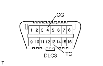
Using SST, connect terminals 13 (TC) and 4 (CG) of the DLC3.
- SST
- 09843-18040
Note
-
Confirm the terminal numbers before connecting them. Connecting the wrong terminals can damage the engine.
-
Check the ignition timing with the cooling fans off.
-
Turn off all the electrical systems and the A/C.
-
When checking the ignition timing, the transmission should be in neutral or park.
-
Using a timing light, check the ignition timing.
Standard ignition timing 8 to 12° BTDC at idle -
Remove SST from the DLC3.
-
Check the ignition timing.
Standard ignition timing 8 to 18° BTDC at idle -
Check that the ignition timing advances immediately when the engine speed is increased.
-
Disconnect the timing light from the engine.
-
Install the engine room side cover LH Click here (for LHD).
-
Install the engine room side cover LH Click here (for RHD).
-
Install the cool air intake duct seal Click here.
-
Install the V-bank cover sub-assembly Click here.
-
-
-
INSPECT IDLE SPEED
-
Warm up and stop the engine.
Tech Tips
A warmed up engine should have an engine coolant temperature of over 80°C (176°F), an engine oil temperature of 60°C (140°F), and the engine speed should be stabilized.
-
When using the intelligent tester:
-
Connect the intelligent tester to the DLC3.
-
Start the engine and run it at idle.
-
Turn the intelligent tester main switch on.
-
Enter the following menus: Powertrain / Engine / Data List / Engine Speed.
Standard idle speed 700 to 800 rpm Note
-
Check the idle speed with the cooling fans off.
-
Turn off all the electrical systems and the A/C.
-
When checking the idle speed, the transmission should be in neutral or park.
Tech Tips
Refer to the intelligent tester operator's manual for further details.
If the idle speed is not as specified, check the air intake system Click here.
-
-
-
When not using the intelligent tester:
-
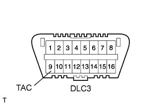
Using SST, connect a tachometer probe to terminal 9 (TAC) of the DLC3.
- SST
- 09843-18040
Note
Confirm the terminal numbers before connecting them. Connecting the wrong terminals can damage the engine.
-
Check the idle speed.
Standard idle speed 700 to 800 rpm Note
-
Check the idle speed with the cooling fans off.
-
Turn off the electrical systems and the A/C.
-
When checking the idle speed, the transmission should be in neutral or park.
Tech Tips
If the speed is not as specified, check the air intake system Click here.
-
-
-
-
INSPECT CO/HC
Tech Tips
This check determines whether or not the idle CO/HC complies with regulations.
-
Start the engine.
-
Keep the engine speed at 2500 rpm for approximately 180 seconds.
-
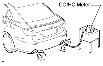
Insert the CO/HC meter testing probe at least 40 cm (1.3 ft) into the tailpipe during idle.
-
Immediately check CO/HC concentration during idle and when running at 2500 rpm.
Tech Tips
-
When performing the 2 mode (with the engine idling/running at 2500 rpm) test, follow the measurement order determined by applicable local regulations.
-
If the CO/HC concentration does not comply with the regulations, perform troubleshooting in the order given below.
-
Check the A/F sensor and heated oxygen sensor operation.
-
See the table below for possible causes, then inspect and correct the applicable causes if necessary.
CO HC Symptom Cause Normal High Rough idle
-
1. Misfiring
-
Incorrect timing
-
Plugs are contaminated, shorted, or gaps are incorrect.
-
2. Leaky intake and exhaust valves
-
3. Leaky cylinder
Low High Rough idle
(Fluctuating HC reading)
-
1. Vacuum leaks
-
PCV hose
-
Intake manifold
-
Throttle body
-
2. Lean mixture causing misfire
High High Rough idle
(Black smoke from exhaust)
-
1. Restricted air filter
-
2. Faulty SFI system
-
Incorrect pressure
-
Defective ECT sensor
-
Faulty ECM
-
Faulty injector
-
Faulty throttle position sensor
-
Faulty MAF sensor
-
-
-
-
CHECK TRANSMISSION CONTROL ECU INITIALIZE
-
VEHICLE PREPARATION FOR HEADLIGHT AIMING ADJUST
-
Prepare the vehicle:
-
Ensure there is no damage or deformation to the body around the headlights.
-
Fill the fuel tank.
-
Make sure that the oil is filled to the specified level.
-
Make sure that the engine coolant is filled to the specified level.
-
Inflate the tires to the appropriate pressure.
-
Unload the trunk and vehicle, ensuring that the spare tire, tools, and jack are in their original positions.
-
Sit a person of average weight (75 kg, 165 lb) in the driver's seat.
-
-
-
PREPARATION FOR HEADLIGHT AIMING
-
Prepare the vehicle:
-
Place the vehicle in a location that is dark enough to clearly observe the cutoff line. The cutoff line is a distinct line, below which light from the headlights can be observed and above which it cannot.
-
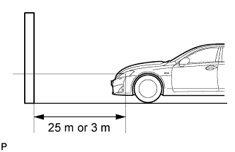
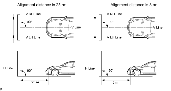
Place the vehicle at a 90° angle to the wall.
-
Create a 25 m (82 ft.) distance between the vehicle (headlight bulb center) and the wall.
-
Make sure that the vehicle is on a level surface.
-
Position the front wheels straight ahead.
-
Bounce the vehicle up and down to settle the suspension.
Note
A distance of 25 m (82 ft.) between the vehicle (headlight bulb center) and the wall is necessary for proper aim adjustment. If sufficient space is not available, secure a distance of exactly 3 m (9.84 ft.) to allow for checking and adjustment of headlight aim. (The size of the target zone will change with the distance, so follow the instructions in the illustration.)
-
-
Prepare a piece of thick white paper (approximately 2 m (6.6 ft.) (height) x 4 m (13.1 ft.) (width)) to use as a screen.
-
Draw a vertical line down the center of the screen (V line).
-
Set the screen as shown in the illustration.
Tech Tips
-
Stand the screen perpendicular to the ground.
-
Align the V line on the screen with the center of the vehicle.
-
-
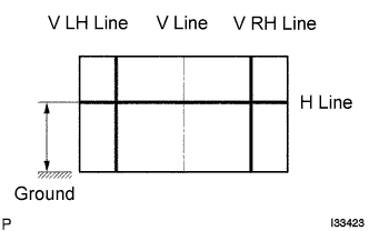
Draw base lines (H, V LH, and V RH lines) on the screen as shown in the illustration.
Tech Tips
-
The base lines differ for "low beam inspection" and "high beam inspection".
-
Mark the headlight bulb center marks on the screen. If the center mark cannot be observed on the headlight, use the center of the headlight bulb or the manufacturer's name marked on the headlight as the center mark.
-
H Line (Headlight height):
Draw a horizontal line across the screen so that it passes through the center marks. The H line should be at the same height as the headlight bulb center marks of the low beam headlights.
-
V LH Line, V RH Line (Center mark position of left-hand (LH) and right-hand (RH) headlights):
Draw two vertical lines so that they intersect the H line at each center mark (aligned with the center of the low beam headlight bulbs).
-
-
-
INSPECT HEADLIGHT AIMING
-
Cover the headlight or disconnect the connector of the headlight on the opposite side to prevent light from the headlight that is not being inspected from affecting the headlight aiming inspection.
CAUTION:
Do not disconnect the HID high voltage connector for the bulb when performing this aiming inspection.
Note
Do not keep the headlight covered for more than 3 minutes. The headlight lens is made of synthetic resin, which may melt or be damaged due to excessive heat.
Tech Tips
When checking the aim of the high beam, cover the low beam or disconnect the connector.
-
Start the engine.
-
Turn on the headlights and check the aiming of each beam.
Tech Tips
-
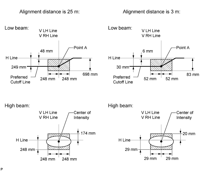
Preferred position for the low beam: Matches preferred cutoff line shown in the illustration.
-
Preferred position for the high beam: Matches center of intensity shown in the illustration.
Tech Tips
-
The illustration shown is for an LHD vehicle, RHD vehicles will project a headlight pattern that is a mirror image.
-
Since the low beam light and the high beam light are a unit, if the aim on the low beam is correct, the high beam should also be correct. However, check both beams just to make sure.
-
If the alignment distance is 25 m (82 ft.):
The low beam cutoff line should be within 48 mm (1.89 in.) and 698 mm (27.4 in.) below the H line as well as 248 mm (9.79 in.) left or right of the V LH or V RH line.
-
If the alignment distance is 3 m (9.84 ft.):
The low beam cutoff line should be within 6 mm (0.227 in.) and 83 mm (3.29 in.) below the H line as well as 29 mm (1.17 in.) left or right of the V LH or V RH line.
-
If the alignment distance is 25 m (82 ft.):
The horizontal line of the preferred low beam cutoff line is 249 mm (9.79 in.) below the H line and point A of the preferred low beam cutoff line is on the V LH or V RH line.
-
If the alignment distance is 3 m (9.84 ft.):
The horizontal line of the preferred low beam cutoff line is 30 mm (1.18 in.) below the H line and point A of the preferred low beam cutoff line is on the V LH or V RH line.
-
If the alignment distance is 25 m (82 ft.):
The high beam center of intensity should be within 174 mm (6.87 in.) above and 248 mm (9.79 in.) below the H line as well as 248 mm (9.79 in.) left or right of the V LH or V RH line.
-
If the alignment distance is 3 m (9.84 ft.):
The high beam center of intensity should be within 20 mm (0.824 in.) above and 29 mm (1.17 in.) below the H line as well as 29 mm (1.17 in.) left or right of the V LH or V RH line.
-
-
-
ADJUST HEADLIGHT AIMING
-
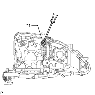
Text in Illustration *1 Aiming Screw A Adjust the aim vertically:
Adjust the aim of each headlight to the specified range by turning aiming screw A with a screwdriver.
-
When adjusting the vertical axis, note the change in the horizontal axis for correction later.
Note
The final turn of the aiming screw should be made in the clockwise direction. If the screw is adjusted too far, loosen it and then retighten it, so that the final turn of the screw is in the clockwise direction.
Tech Tips
-
The low beam light and the high beam light are a unit. Adjusting the aim on the low beam to the correct position should also result in the high beam adjustment being correct.
-
When adjusting the vertical axis of the headlight, the horizontal axis will also change. It is necessary to adjust the vertical position first, and then correct the horizontal position.
-
If it is not possible to correctly adjust headlight aim, check bulb, headlight unit, and headlight unit reflector installation.
-
The headlight aim moves up and to the left when turning the aiming screw clockwise, and it moves down and to the right when turning the aiming screw counterclockwise.
-
Confirm the direction of rotation of the aiming screw by observing it while it is being adjusted. Due to the position of the screwdriver, the direction of rotation of the adjusting screw can be different than the direction of rotation of the screwdriver being used to adjust it.
-
-
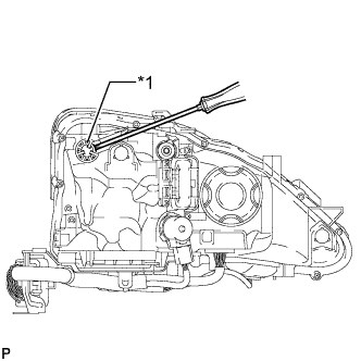
Text in Illustration *1 Aiming Screw B Adjust the aim horizontally:
Adjust the aim of each headlight to the specified range by turning each aiming screw B with a screwdriver.
Note
The final turn of the aiming screw should be made in the clockwise direction. If the screw is adjusted too far, loosen it and then retighten it, so that the final turn of the screw is in the clockwise direction.
Tech Tips
-
The low beam light and the high beam light are a unit. Adjusting the aim on the low beam to the correct position should also result in the high beam adjustment being correct.
-
Confirm the direction of rotation of the aiming screw by observing it while it is being adjusted. Due to the position of the screwdriver, the direction of rotation of the adjusting screw can be different than the direction of rotation of the screwdriver being used to adjust it.
-
If it is not possible to correctly adjust headlight aim, check bulb, headlight unit, and headlight unit reflector installation.
-
-