ENGINE ASSEMBLY REMOVAL

-
PRECAUTION
-
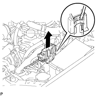
REMOVE V-BANK COVER SUB-ASSEMBLY
-
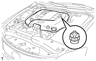
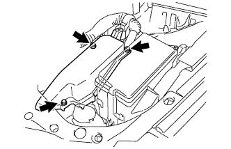
Hold the front of the V-bank cover sub-assembly and raise it to disengage the 2 clips on the front of the cover. Continue to raise the cover to disengage the 2 clips on the rear of the cover and remove the V-bank cover sub-assembly.
Note
Attempting to disengage both front and rear clips at the same time may cause the cover to break.
-
-
REMOVE COOL AIR INTAKE DUCT SEAL
-
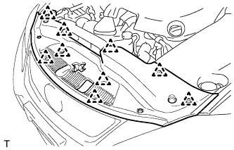
Remove the 9 clips and cool air intake duct seal.
-
-
REMOVE ENGINE ROOM SIDE COVER LH (for LHD)
-

Remove the 5 clips and engine room side cover LH.
-
-
REMOVE ENGINE ROOM SIDE COVER LH (for RHD)
-
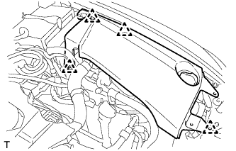
Remove the 4 clips and engine room side cover LH.
-
-
REMOVE ENGINE ROOM SIDE COVER RH (for LHD)
-
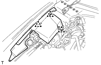
Remove the 3 clips and engine room side cover RH.
-
-
REMOVE ENGINE ROOM SIDE COVER RH (for RHD)
-
Remove the 4 clips and engine room side cover RH.
-
-
PLACE FRONT WHEELS FACING STRAIGHT AHEAD
-
DISCHARGE REFRIGERANT FROM REFRIGERATION SYSTEM
-
Start up the engine.
-
Turn the A/C switch on.
-
Operate the cooler compressor at an engine speed of approximately 1000 rpm for 5 to 6 minutes to circulate the refrigerant and collect the compressor oil remaining in each component into the cooler compressor.
-
Stop the engine.
-
Recover the refrigerant from the A/C system using a refrigerant recovery unit.
-
-
DISCHARGE FUEL SYSTEM PRESSURE
-
DISCONNECT CABLE FROM NEGATIVE BATTERY TERMINAL
-
Disable the auto tilt away function by changing the customize parameter Click here.
Note
Record the current customize parameter setting (whether the auto tilt away function is enabled or disabled) in order to restore the current setting after finishing this operation.
Tech Tips
Performing the above operation disables the auto tilt away function when the engine switch is turned off.
-
Turn the engine switch on (IG). Operate the tilt and telescopic switch to fully extend and lower the steering column assembly.
-
Turn the engine switch off and disconnect the cable from the negative (-) battery terminal.
CAUTION:
Wait at least 90 seconds after disconnecting the cable from the negative (-) battery terminal to disable the SRS system.
Note
When disconnecting the cable, some systems need to be initialized after the cable is reconnected Click here.
-
-
REMOVE FRONT WHEEL
-
REMOVE ENGINE UNDER COVER
-
REMOVE REAR ENGINE UNDER COVER LH
-
REMOVE REAR ENGINE UNDER COVER RH
-
REMOVE NO. 2 ENGINE UNDER COVER
-
REMOVE FRONT LOWER SUSPENSION MEMBER PROTECTOR
-
Remove the 4 bolts and the front lower suspension member protector.
-
-
REMOVE ENGINE UNDER COVER AIR GUIDE BRACKET
-
Remove the 2 bolts and engine under cover air guide bracket.
-
-
DRAIN ENGINE OIL
-
Remove the oil filler cap.
-
Remove the oil pan drain plug and drain the engine oil into a container.
-
Install a new gasket and the oil pan drain plug.
- Torque:
- 40 N*m { 408 kgf*cm, 30 ft.*lbf }
-
-
DRAIN ENGINE COOLANT
-
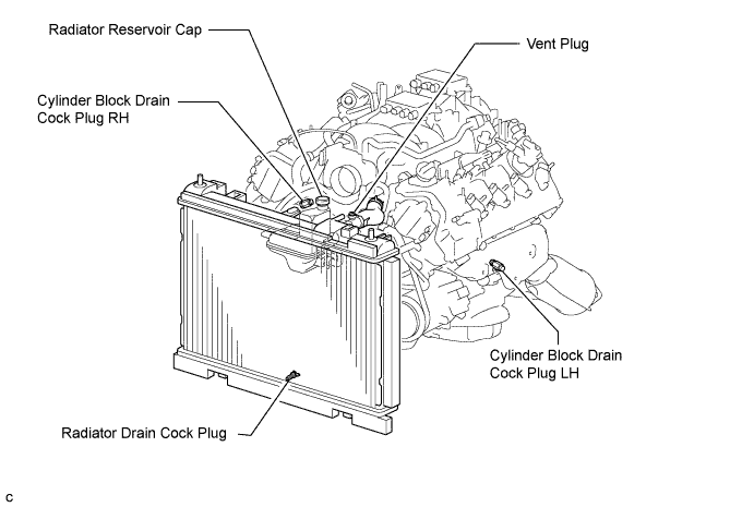
Loosen the radiator drain cock plug.
CAUTION:
Do not loosen the radiator drain cock plug while the engine and radiator are still hot. Pressurized, hot engine coolant and steam may be released and cause serious burns.
Tech Tips
Collect the coolant in a container and dispose of it according to local regulations.
-
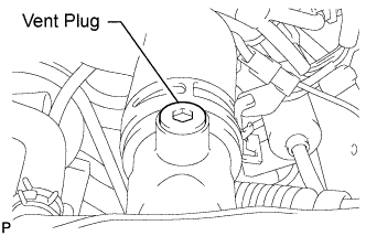
Remove the radiator reservoir cap, and using a 6 mm socket hexagon wrench, remove the vent plug.
-
Drain coolant.
-
Loosen the 2 cylinder block drain cock plugs.
-
-
DRAIN AUTOMATIC TRANSMISSION FLUID
-
Remove the drain plug and gasket, and drain the ATF.
-
Install a new gasket and the drain plug.
- Torque:
- 20 N*m { 204 kgf*cm, 15 ft.*lbf }
-
-
REMOVE NO. 1 AIR CLEANER INLET
-
Remove the bolt, clip and No. 1 air cleaner inlet.
-
-
REMOVE AIR CLEANER CAP SUB-ASSEMBLY
-
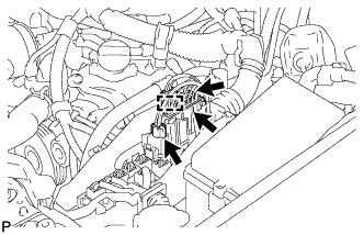
Loosen the 2 hose clamps and separate the 2 ventilation hoses.
-
Disconnect the mass air flow meter connector and separate the wire harness clamp.
-
Loosen the hose clamp and separate the air cleaner hose.
-
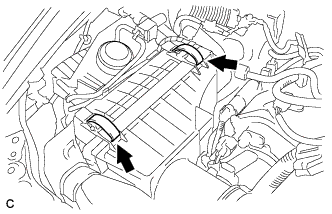
Unlock the 2 clamps and remove the air cleaner cap sub-assembly.
-
-
REMOVE AIR CLEANER CASE SUB-ASSEMBLY
-
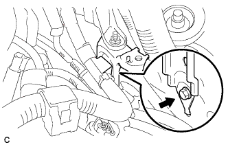
Remove the 2 clamps and disconnect the vacuum hose.
-
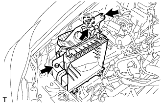
Remove the clamp and disconnect the vacuum switching valve connector.
-
Remove the 2 bolts and air cleaner case sub-assembly.
-
-
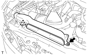
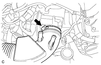
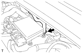
DISCONNECT RESERVE TANK OUTLET HOSE
-
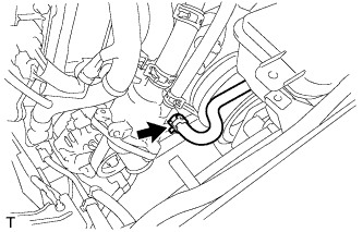
Disconnect the reserve tank outlet hose.
-
-
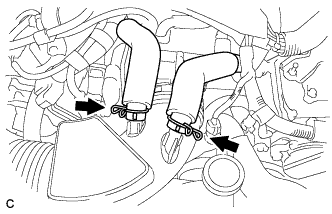
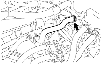
DISCONNECT NO. 1 RADIATOR HOSE
-
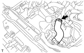
Disconnect the No. 1 radiator hose.
-
-
DISCONNECT NO. 2 RADIATOR HOSE
-
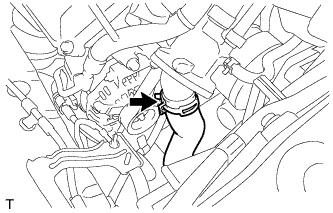
Disconnect the No. 2 radiator hose.
-
-
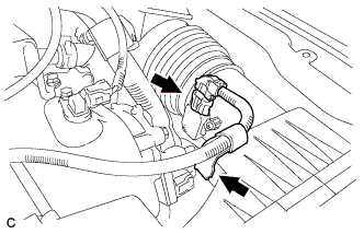
DISCONNECT NO. 2 OIL COOLER INLET HOSE
-
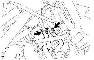
Disconnect the No. 2 oil cooler inlet hose.
-
-
DISCONNECT NO. 2 OIL COOLER OUTLET HOSE
-
Disconnect the No. 2 oil cooler outlet hose.
-
-
DISCONNECT HEATER WATER HOSE INLET A
-
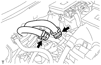
Disconnect the heater water inlet hose A.
-
-
DISCONNECT HEATER WATER OUTLET HOSE A
-
Disconnect the heater water outlet hose A.
-
-
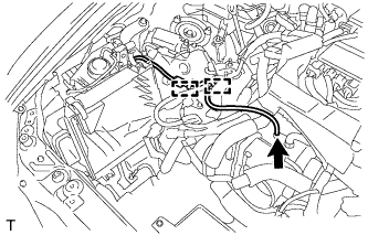
DISCONNECT VACUUM HOSE ASSEMBLY (for LHD)
-
Disconnect the vacuum hose assembly from the hose clamp.
-
Disconnect the vacuum hose assembly from the intake air surge tank assembly.
-
-
DISCONNECT VACUUM HOSE ASSEMBLY (for RHD)
-
Disconnect the vacuum hose assembly from the intake air surge tank assembly.
-
-
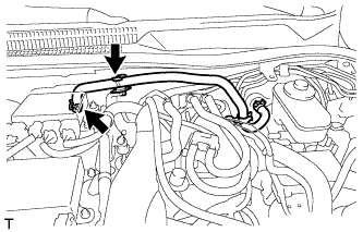
DISCONNECT NO. 2 FUEL VAPOR FEED HOSE
-
Disconnect the No. 2 fuel vapor feed hose.
-
-
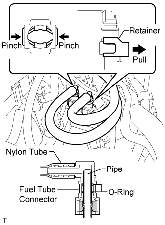
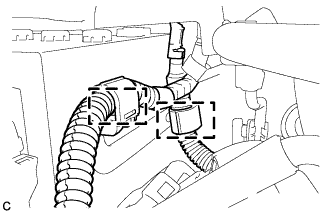
DISCONNECT NO. 3 FUEL HOSE
-
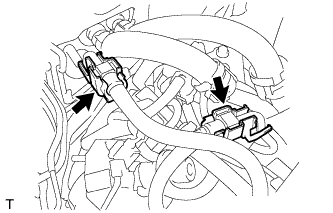
Remove the 2 fuel pipe clamps.
-
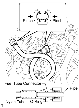
Pinch the fuel tube connector and then pull out the No. 3 fuel hose.
Note
-
Check for any dirt and foreign matter contamination in the pipe and around the connector. Clean if necessary. Foreign matter may damage the O-rings or cause leaks in the seal between the pipe and connector.
-
Do not use any tools to separate the pipe and connector.
-
Do not forcefully bend or twist the nylon tube.
-
Check for any dirt and foreign matter on the pipe seal surface. Clean if necessary.
-
Put the pipe and connector ends in plastic bags to prevent damage and dirt contamination.
-
If the pipe and connector are stuck together, pinch the tube between your fingers and turn it carefully to free it. Then disconnect the hose.
-
-
-
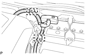
DISCONNECT NO. 1 FUEL HOSE
-
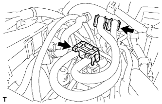
Remove the 2 fuel pipe clamps.
-
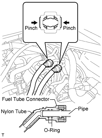
Pinch the 2 fuel tube connector and then pull out the No. 1 fuel hose.
Note
-
Check for any dirt and foreign matter contamination in the pipe and around the connector. Clean if necessary. Foreign matter may damage the O-rings or cause leaks in the seal between the pipe and connector.
-
Do not use any tools to separate the pipe and connector.
-
Do not forcefully bend or twist the nylon tube.
-
Check for any dirt and foreign matter on the pipe seal surface. Clean if necessary.
-
Put the pipe and connector ends in plastic bags to prevent damage and dirt contamination.
-
If the pipe and connector are stuck together, pinch the tube between your fingers and turn it carefully to free it. Then disconnect the hose.
-
-
Lift up the retainer to release its lock.
-
Pinch the 2 fuel tube connectors and then pull out the No. 1 fuel hose.
Note
-
Check for any dirt and foreign matter contamination in the pipe and around the connector. Clean if necessary. Foreign matter may damage the O-rings or cause leaks in the seal between the pipe and connector.
-
Do not use any tools to separate the pipe and connector.
-
Do not forcefully bend or twist the nylon tube.
-
Check for any dirt and foreign matter on the pipe seal surface. Clean if necessary.
-
Put the pipe and connector ends in plastic bags to prevent damage and dirt contamination.
-
If the pipe and connector are stuck together, pinch the tube between your fingers and turn it carefully to free it. Then disconnect the hose.
-
-
-
DISCONNECT NO. 1 COOLER REFRIGERANT SUCTION HOSE
-
Disconnect the connector and 2 clamps.
-
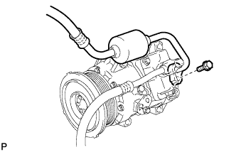
Remove the bolt and disconnect the No. 1 cooler refrigerant suction hose from the compressor.
-
Remove the O-ring from the cooler refrigerant suction hose.
Note
Seal the openings of the disconnected parts using vinyl tape to prevent moisture and foreign matter from entering.
-
-
DISCONNECT DISCHARGE HOSE SUB-ASSEMBLY
-
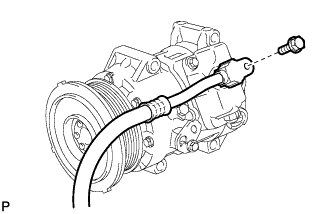
Remove the bolt and disconnect the discharge sub-assembly from the compressor.
-
Remove the O-ring from the discharge sub-assembly.
Note
Seal the openings of the disconnected parts using vinyl tape to prevent moisture and foreign matter from entering.
-
-
REMOVE BATTERY (for LHD)
-
Disconnect the 2 clamps.
-
Disconnect the cable from the positive (+) battery terminal.
-
Remove the nut and the battery clamp.
-
Remove the battery insulator.
-
Remove the battery.
-
-
REMOVE BATTERY (for RHD)
-
Disconnect the 2 clamps.
-
Disconnect the cable from the positive (+) battery terminal.
-
Remove the nut and the battery clamp.
-
Remove the battery insulator.
-
Remove the battery.
-
-
REMOVE NO. 1 BATTERY TRAY SUPPORT
-
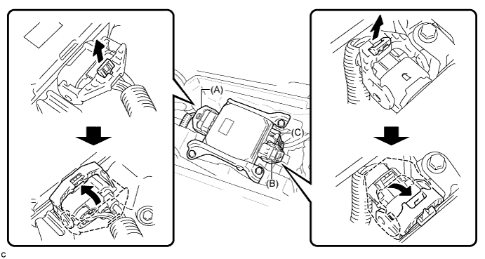
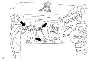
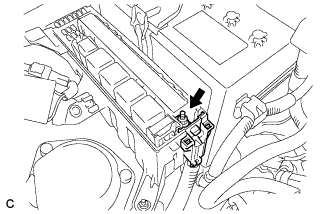
REMOVE POWER STEERING ECU ASSEMBLY
-
Release the locks of the 2 power steering ECU assembly connectors (A) and (B).
-
Disconnect the connectors (A), (B) and (C) from the power steering ECU assembly.
-
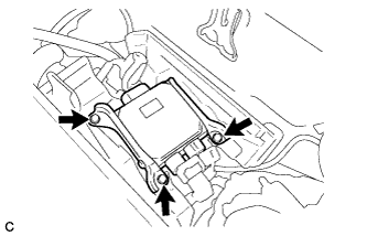
Remove the 3 bolts.
-
Remove the power steering ECU assembly.
-
-
REMOVE BATTERY TRAY (for LHD)
-
Remove the 3 bolts and battery tray.
-
Remove the 2 bolts and nut and separate the No. 7 engine room relay block.
-
-
REMOVE BATTERY TRAY (for RHD)
-
Remove the 3 bolts and battery tray.
-
Remove the 2 bolts and nut and separate the No. 7 engine room relay block.
-
-
REMOVE WIRE HARNESS CLAMP BRACKET (for LHD)
-
Remove the bolt and separate the wire harness clamp bracket.
-
Separate the wire harness clamp from the wire harness clamp bracket.
-
-
REMOVE WIRE HARNESS CLAMP BRACKET (for RHD)
-
Remove the bolt and separate the wire harness clamp bracket.
-
Separate the wire harness clamp from the wire harness clamp bracket.
-
-
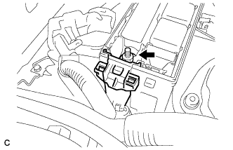
REMOVE ENGINE ROOM ECU COVER
-
Remove the 3 bolts and the engine room ECU cover.
Note
-
Remove all water from on and around the engine room ECU cover.
-
Perform the inspection indoors to avoid rain.
-
Be sure to prevent water intrusion to the ECM (connectors and screw holes).
-
-
-
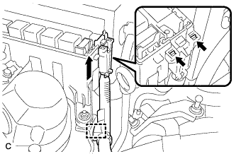
DISCONNECT WIRE HARNESS
-
Remove the 3 connectors and connector clamp.
-
Detach the claw and disconnect the No. 4 connector holder.
-
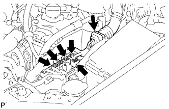
Disconnect the 5 connectors and grommet from the ECM box.
-
Remove the nut, and disconnect the battery positive (+) cable and clamp from the battery (for LHD).
-
Remove the nut, and disconnect the battery positive (+) cable and clamp from the battery (for RHD).
-
Remove the No. 1 engine room relay block cover.
-
Remove the nut (for LHD).
-
Remove the nut (for RHD).
-
Disconnect the clamp, detach the 2 claws and disconnect the wire harness from the No. 1 relay block (for LHD).
-
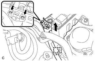
Disconnect the clamp, detach the 2 claws and disconnect the wire harness from the No. 1 relay block (for RHD).
-
Remove the bolt and disconnect the ground cable.
-
Remove the bolt, and disconnect the clamp and ground cable.
-
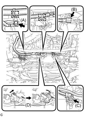
Disconnect the power steering wire harness (for LHD).
-
Remove bolt (A) to disconnect the earth wire from the bracket.
-
Remove the 2 clamps to disconnect the wire harness from the bracket.
-
Disconnect 2 connectors (B) and (C) from the power steering link assembly.
-
Release the lock of connector (D) and disconnect connector (D) from the power steering link assembly.
-
-
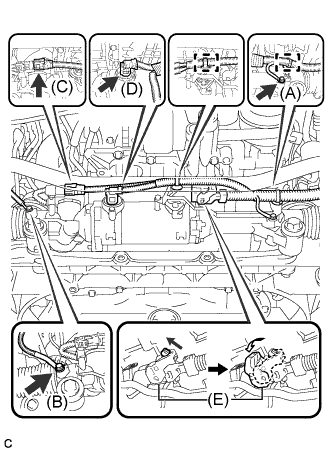
Disconnect the power steering wire harness (for RHD).
-
Remove 2 bolts (A) and (B) to disconnect the earth wire.
-
Remove the 2 clamps to disconnect the wire harness from the bracket.
-
Disconnect 2 connectors (C) and (D) from the power steering link assembly.
-
Release the lock of connector (E) and disconnect connector (E) from the power steering link assembly.
-
-
Remove the bolt and disconnect the ground cable.
-
-
REMOVE NO. 2 FLOOR UNDER COVER
-
Remove the 6 clips, 3 grommets, and No. 2 floor under cover.
-
-
REMOVE NO. 1 FLOOR UNDER COVER
-
Remove the 5 clips, 3 grommets, and No. 1 floor under cover.
-
-
REMOVE TAIL EXHAUST PIPE ASSEMBLY
-
Remove the 2 bolts and 2 compression springs.
-
Remove the tail exhaust pipe assembly from the 6 exhaust pipe supports.
-
Remove the gasket from the front exhaust pipe assembly.
-
-
REMOVE REAR NO. 1 FLOOR PANEL BRACE
-
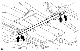
Remove the 4 bolts and rear No. 1 floor panel brace.
-
-
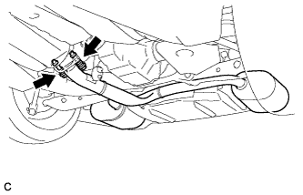
REMOVE FRONT CENTER FLOOR BRACE
-
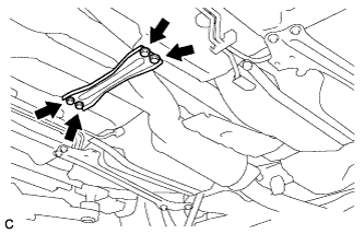
Remove the 4 bolts and front center floor brace.
-
-
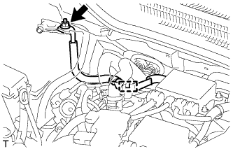
REMOVE HEATED OXYGEN SENSOR
-
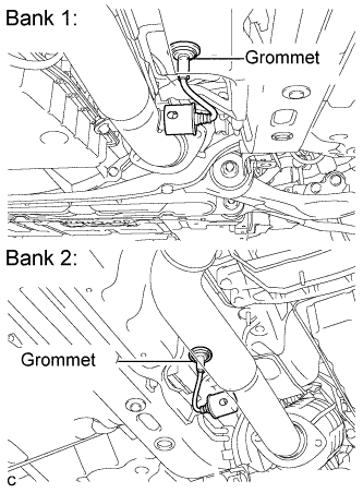
Remove the grommets of the heated oxygen sensors.
-
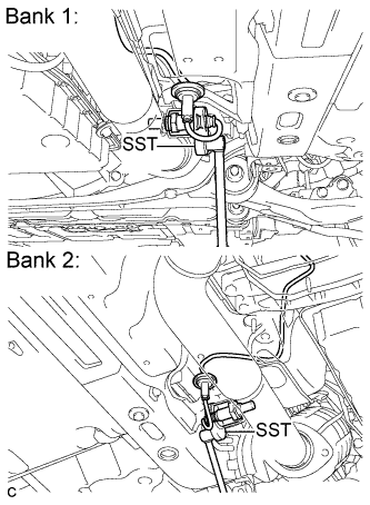
Using SST, loosen the heated oxygen sensors, and disconnect the sensors by hand.
- SST
- 09224-00010
-
-
REMOVE FRONT EXHAUST PIPE ASSEMBLY
-
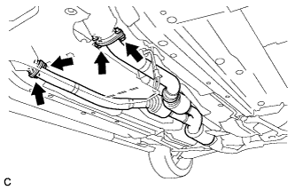
Remove the 4 bolts, 4 nuts and front exhaust pipe assembly.
-
Remove the 2 gaskets from the exhaust manifold RH and exhaust manifold LH.
-
-
REMOVE FRONT NO. 1 FLOOR HEAT INSULATOR
-
Remove the 4 nuts, 2 bolts and front No. 1 floor heat insulator.
-
-
REMOVE OUTSIDE AIR GUIDE PLATE RH
-
Remove the 4 nuts and outside air guide plate RH.
-
-
REMOVE PROPELLER SHAFT WITH CENTER BEARING ASSEMBLY
-
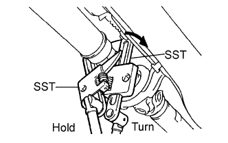
Using SST, loosen the adjusting nut until it can be turned by hand.
- SST
- 09922-10010
Tech Tips
Use 2 of the same SST.
-
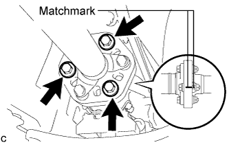
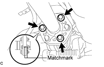
Put matchmarks on the transmission companion flange, flexible coupling and intermediate shaft.
-
Remove the 3 bolts, 3 washers and 3 nuts.
Note
Do not separate the propeller shaft and flexible coupling.
-
Put matchmarks on the differential companion flange, flexible coupling and propeller shaft.
-
Remove the 3 bolts, 3 washers and 3 nuts.
Note
Do not separate the propeller shaft and flexible coupling.
-
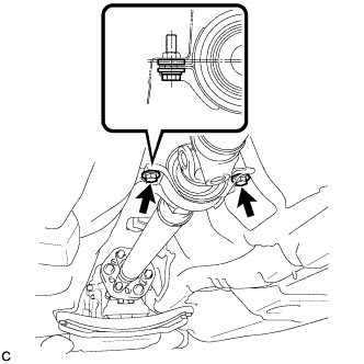
Remove the 2 center support bearing set bolts and 2 center support bearing washers.
Tech Tips
Some vehicles are not equipped with center support bearing washers.
-
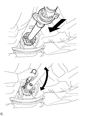
Push the propeller shaft with center bearing assembly straight ahead to compress and pull out the propeller shaft with center bearing assembly from the differential centering pin.
Note
Press the propeller shaft straight ahead to keep the transmission and intermediate shaft aligned straight.
Tech Tips
If it is difficult to separate the flange from the flexible coupling, pry it using a screwdriver.
-
Pull the propeller shaft outward from the rear of the vehicle.
Note
Do not separate the intermediate shaft and propeller shaft.
-
-
SEPARATE FRONT SHOCK ABSORBER ASSEMBLY LH
-
Support the front lower suspension arm with a jack.
Note
Be sure to place a wooden block between the jack and the front lower suspension arm to avoid damage.
-
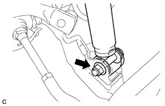
Remove the nut while holding the bolt.
Note
Do not remove the bolt.
-
-
SEPARATE FRONT SHOCK ABSORBER ASSEMBLY RH
Tech Tips
Perform the same procedure for the LH side.
-
SEPARATE STEERING KNUCKLE LH
-
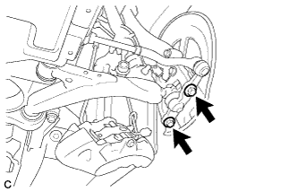
Remove the 2 bolts and separate the steering knuckle with axle assembly.
-
-
SEPARATE STEERING KNUCKLE RH
Tech Tips
Perform the same procedure for the LH side.
-
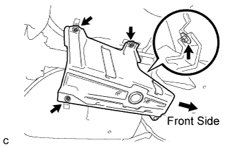
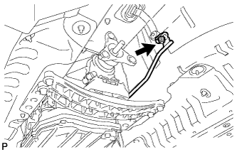
SEPARATE HEIGHT CONTROL SENSOR LINK SUB-ASSEMBLY
-
Remove the nut and separate the height control sensor link assembly.
-
-
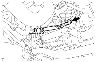
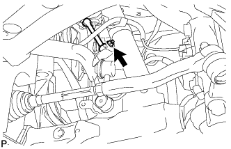
SEPARATE STEERING SLIDING YOKE SUB-ASSEMBLY
-
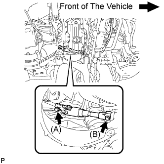
Loosen the bolt (A) and remove the bolt (B), then slide the steering sliding yoke sub-assembly.
Note
-
Do not remove the bolt (A).
-
Do not separate the steering sliding yoke sub-assembly from the power steering gear assembly.
-
-
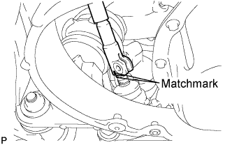
Put matchmarks on the steering sliding yoke sub-assembly and the power steering link assembly.
-
Separate the steering sliding yoke sub-assembly from the power steering link assembly.
-
-
REMOVE STEERING COLUMN ASSEMBLY
-
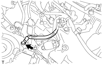
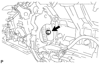
DISCONNECT FLOOR SHIFT GEAR SHIFTING ROD SUB-ASSEMBLY
-
Remove the nut and disconnect the floor shift gear shifting rod.
-
-
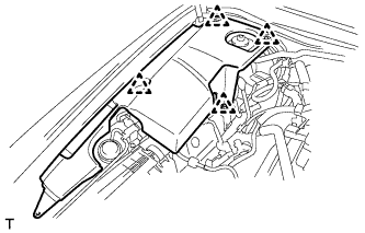
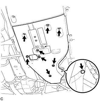
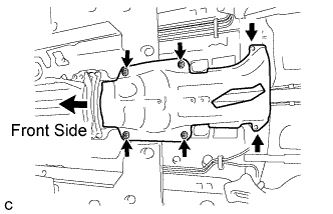
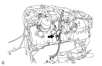
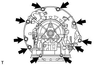
REMOVE ENGINE AND TRANSMISSION
-
Set the engine lifter.
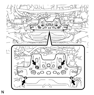
-
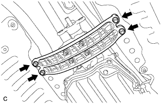
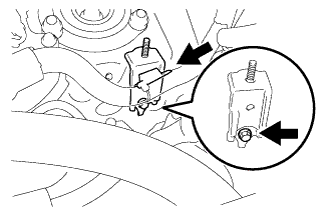
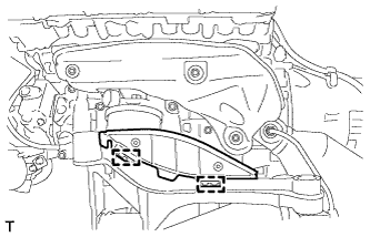
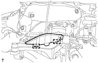
Remove the 4 bolts and disconnect the rear engine mounting member.
-
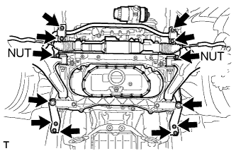
Remove the 10 bolts and 2 nuts shown in the illustration.
-
Operate the engine lifter to slowly remove the engine from the vehicle.
Note
Make sure that the engine is clear of all wiring and hoses.
-
-
INSTALL ENGINE HANGER
-
Install the 2 engine hangers with the 2 bolts as shown in the illustration.
Engine Hanger Part No. Item Part No. Engine hanger 12081-38020 Bolt 90119-14120 - Torque:
- 43 N*m { 438 kgf*cm, 32 ft.*lbf }
-
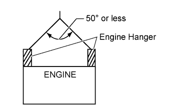
Attach an engine sling device and hang the engine with a chain block.
Note
When hanging the engine, make sure to hang the engine with the chains at an angle of 50° or less. Otherwise, the engine or engine hangers may be damaged.
-
-
REMOVE ENGINE OIL LEVEL DIPSTICK
-
REMOVE ENGINE OIL LEVEL DIPSTICK GUIDE
-
Remove the bolt and oil level dipstick guide sub-assembly.
-
Remove the O-ring from the oil level dipstick guide sub-assembly.
-
-
REMOVE ENGINE UNDER COVER SUB-ASSEMBLY LH
-
Remove the 2 clamps and engine under cover sub-assembly LH from the front suspension crossmember sub-assembly.
-
-
REMOVE ENGINE UNDER COVER SUB-ASSEMBLY RH
-
Remove the 2 clamps and engine under cover sub-assembly RH from the front suspension crossmember sub-assembly.
-
-
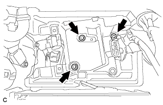
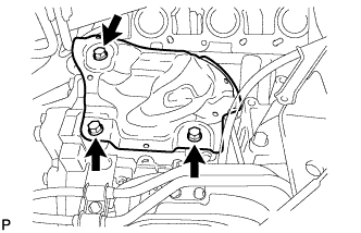
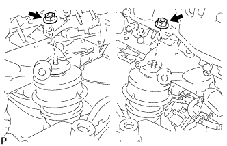
REMOVE ENGINE MOUNTING DAMPER
-
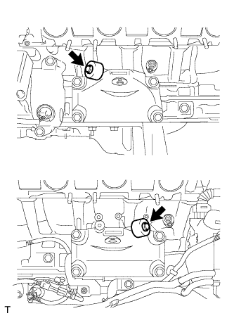
Remove the 2 bolts and 2 engine mounting dampers.
-
-
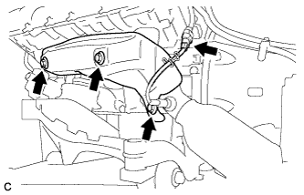
REMOVE NO. 1 EXHAUST MANIFOLD HEAT INSULATOR
-
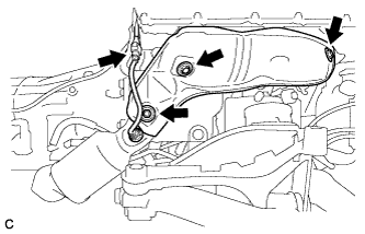
Disconnect the air fuel ratio sensor connector.
-
Remove the 3 bolts and No. 1 exhaust manifold heat insulator.
-
-
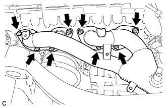
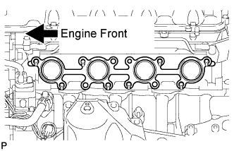
REMOVE EXHAUST MANIFOLD SUB-ASSEMBLY RH
-
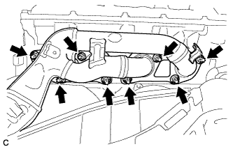
Remove the 8 nuts and exhaust manifold sub-assembly RH.
-
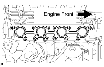
Remove the gasket.
-
-
REMOVE NO. 2 EXHAUST MANIFOLD HEAT INSULATOR
-
Disconnect the air fuel ratio sensor connector.
-
Remove the 3 bolts and No. 2 exhaust manifold heat insulator.
-
-
REMOVE EXHAUST MANIFOLD SUB-ASSEMBLY LH
-
Remove the 8 nuts and exhaust manifold sub-assembly LH.
-
Remove the gasket.
-
-
REMOVE NO. 3 EXHAUST MANIFOLD HEAT INSULATOR
-
Remove the 3 bolts and No. 3 exhaust manifold heat insulator.
-
-
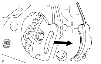
REMOVE V-RIBBED BELT
-
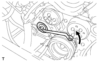
Rotate the V-ribbed belt tensioner pulley counterclockwise to loosen the V-ribbed belt tensioner.
Tech Tips
The pulley bolt for the V-ribbed belt tensioner is reverse threaded.
-
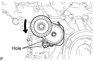
While turning the V-ribbed belt tensioner counterclockwise, align the holes. Insert a bar of φ5 mm (0.197 in.) into the holes to secure the V-ribbed belt tensioner in place.
-
Remove the V-ribbed belt.
-
-
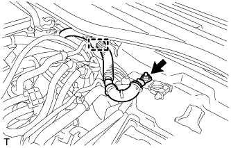
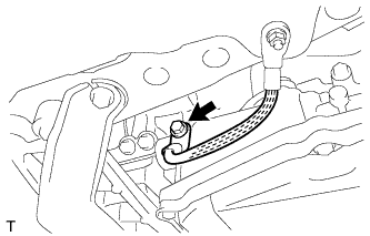
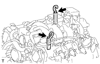
SEPARATE BREATHER PLUG HOSE
-
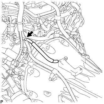
Separate the breather plug hose from the transmission breather assembly.
-
-
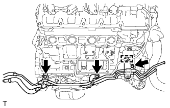
DISCONNECT WIRE HARNESS AND CONNECTORS
-
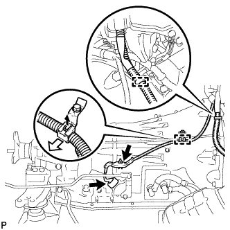
Disconnect the park/neutral position switch connector.
-
Remove the nut and disconnect the 2 wire harness clamps.
-
Disconnect the transmission wire connector.
Tech Tips
Detach the claw, press down the lever, and then disconnect the transmission wire connector.
-
Remove the 2 bolts and disconnect the wire harness clamp.
-
-
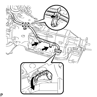
REMOVE OIL COOLER TUBE
-
Disconnect the wire harness clamp from the oil cooler tube.
-
Remove the 2 bolts, nut, clamp and oil cooler tube.
-
-
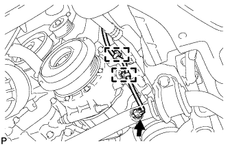
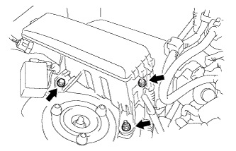
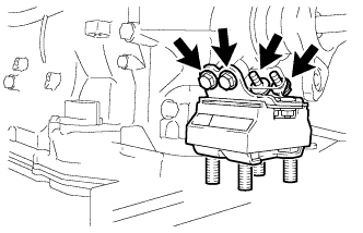
REMOVE COMPRESSOR AND PULLEY
-
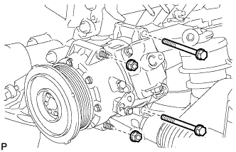
Remove the 2 bolts and 2 nuts.
-
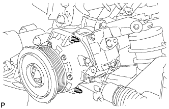
Using an E8 "TORX" socket, remove the 2 stud bolts and compressor.
-
-
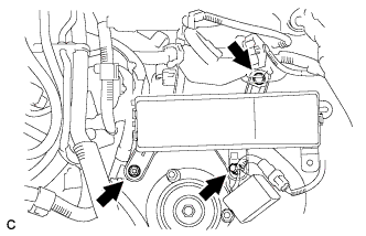
REMOVE GENERATOR ASSEMBLY
-
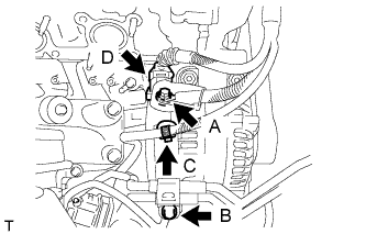
Remove nut A, and disconnect the harness from the +B terminal.
-
Remove bolt B, and disconnect the oil cooler tube.
-
Remove clamp C.
-
Disconnect generator connector D.
-
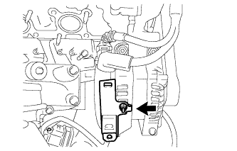
Remove the nut and the wire harness bracket.
-
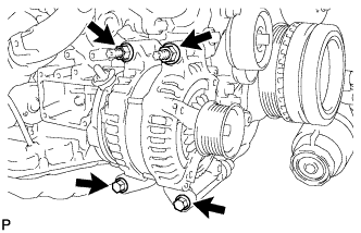
Remove the 2 bolts and 2 nuts.
-
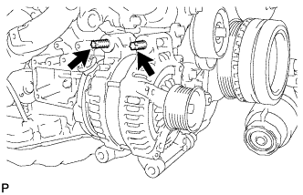
Using an E8 "TORX" socket wrench, remove the 2 stud bolts and generator.
-
-
REMOVE STARTER ASSEMBLY
-
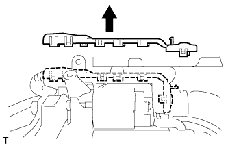
Detach the 11 claws and remove the terminal upper cover.
-
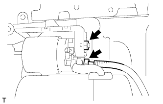
Disconnect the starter connector.
-
Remove the nut and disconnect the wire harness.
-
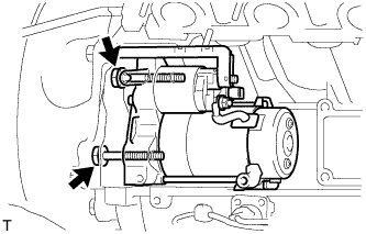
Remove the 2 bolts and starter assembly.
-
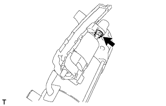
Remove the nut and terminal lower cover.
-
Remove the flywheel housing side cover.
-
-
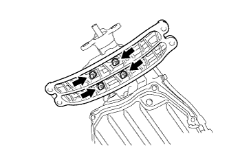
REMOVE DRIVE PLATE AND TORQUE CONVERTER CLUTCH SETTING BOLT
-
Turn the crankshaft to gain access to each bolt.
-
While holding the crankshaft pulley nut with a wrench, remove the 6 bolts.
-
-
REMOVE AUTOMATIC TRANSMISSION ASSEMBLY
-
Remove the 10 bolts.
-
Separate and remove the automatic transmission.
-
-
REMOVE REAR ENGINE MOUNTING MEMBER
-
Remove the 4 nuts and rear engine mounting member.
-
-
REMOVE REAR ENGINE MOUNTING INSULATOR ASSEMBLY
-
Remove the 4 bolts and rear engine mounting insulator.
-
-
REMOVE DRIVE PLATE AND RING GEAR SUB-ASSEMBLY
-
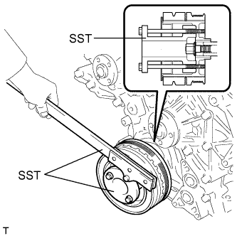
Using SST, hold the crankshaft.
- SST
- 09213-38010
- 09330-00021
-
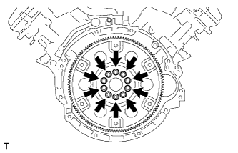
Remove the 10 bolts, drive plate spacer RR, drive plate and ring gear sub-assembly and crankshaft angle sensor rotor.
-
-
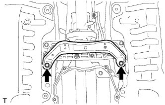
REMOVE FRONT SUSPENSION CROSSMEMBER SUB-ASSEMBLY
-
Remove the 2 nuts, then remove the front suspension crossmember sub-assembly from the engine.
-
-
REMOVE FRONT ENGINE MOUNTING INSULATOR
-
Remove the 2 engine mounting spacers.
-
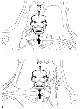
Remove the 2 nuts and 2 front engine mounting insulators from the front suspension crossmember sub-assembly.
-