CYLINDER HEAD GASKET INSTALLATION

-
INSPECT CYLINDER HEAD SET BOLT
-
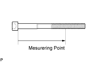
Using a vernier caliper, measure the minimum diameter of the elongated thread at the measuring point.
Standard outside diameter 10.85 to 11.00 mm (0.427 to 0.433 in.) Minimum outside diameter 10.6 mm (0.417 in.) Measuring point 90 mm (3.54 in.) for intake side bolt 85 mm (3.35 in.) for exhaust side bolt Tech Tips
-
If a visual check shows no excessively thin areas, check the center of the bolt (see illustration) and find the area that has the smallest diameter.
-
If the diameter is less than the minimum, replace the cylinder head set bolt.
-
-
-
INSTALL NO. 2 CYLINDER HEAD GASKET (for Bank 1)
-
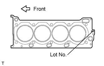
Place a new No. 2 cylinder head gasket the cylinder block surface with the Lot No. stamp facing upward.
Note
-
Be sure to place the gasket in the correct direction.
-
Gently place the cylinder head on the cylinder block in order to prevent damaging the gasket.
-
-
-
INSTALL CYLINDER HEAD SUB-ASSEMBLY (for Bank 1)
-
Place the cylinder head sub-assembly on the cylinder block.
Note
-
Clean and degrease all contact surface.
-
Inspect and clean each cylinder head set bolt and installation hole.
-
-
Apply a light coat of engine oil to the threads and under the heads of the cylinder head set bolts.
Tech Tips
Tighten the cylinder head set bolts in 3 progressive steps.
-
Step 1:
-
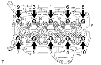
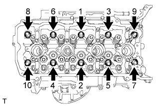
Using a 10 mm bi-hexagon wrench, install and uniformly tighten the 10 cylinder head set bolts with the plate washers in several steps, in the sequence shown in the illustration.
- Torque:
- 36 N*m { 367 kgf*cm, 27 ft.*lbf }
-
-
Step 2:
-
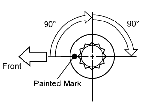
Mark each cylinder head set bolt head with paint as shown in the illustration.
-
Tighten the cylinder head set bolts another 90° in the sequence shown in step 1.
-
-
Step 3:
-
Tighten the cylinder head set bolts by an additional 90° in the sequence shown in step 1.
-
Check that the painted marks are now facing rearward.
-
-
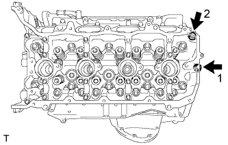
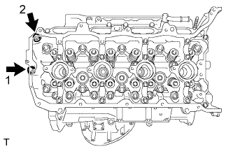
Install the 2 bolts in the sequence shown in the illustration.
- Torque:
- 21 N*m { 214 kgf*cm, 15 ft.*lbf }
-
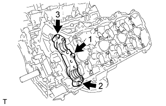
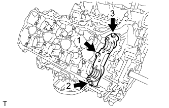
Place the camshaft housing on the cylinder head sub-assembly.
-
Temporarily tighten the camshaft housing with the 3 bolts in the sequence shown in the illustration.
- Torque:
- 10 N*m { 102 kgf*cm, 7 ft.*lbf }
-
Fully tighten the 3 bolts in the sequence shown in the illustration.
- Torque:
- 24 N*m { 245 kgf*cm, 18 ft.*lbf }
-
-
INSTALL CYLINDER HEAD GASKET (for Bank 2)
-
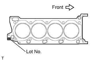
Place a new cylinder head gasket onto the cylinder block surface with the Lot No. stamp facing upward.
Note
-
Be sure to place the gasket in the correct direction.
-
Gently place the cylinder head onto the cylinder block in order to prevent damaging the gasket.
-
-
-
INSTALL CYLINDER HEAD SUB-ASSEMBLY (for Bank 2)
-
Place the cylinder head sub-assembly on the cylinder block.
Note
-
Clean and degrease all contact surface.
-
Inspect and clean each cylinder head set bolt and installation hole.
-
-
Apply a light coat of engine oil to the threads and under the heads of the cylinder head set bolts.
Tech Tips
Tighten the cylinder head set bolts in 3 progressive steps.
-
Step 1:
-
Using a 10 mm bi-hexagon wrench, install and uniformly tighten the 10 cylinder head set bolts with the plate washers in several steps, in the sequence shown in the illustration.
- Torque:
- 36 N*m { 367 kgf*cm, 27 ft.*lbf }
-
-
Step 2:
-
Mark each cylinder head set bolt head with paint as shown in the illustration.
-
Tighten the cylinder head set bolts another 90° in the sequence shown in step 1.
-
-
Step 3:
-
Tighten the cylinder head set bolts by an additional 90° in the sequence shown in step 1.
-
Check that the painting marks are now facing rearward.
-
-
Install the 2 cylinder head set bolts in the sequence shown in the illustration.
- Torque:
- 21 N*m { 214 kgf*cm, 15 ft.*lbf }
-
Place the camshaft housing on the cylinder head sub-assembly.
-
Temporarily tighten the camshaft housing with the 3 bolts in the sequence shown in the illustration.
- Torque:
- 10 N*m { 102 kgf*cm, 7 ft.*lbf }
-
Fully tighten the 3 bolts in the sequence shown in the illustration.
- Torque:
- 24 N*m { 245 kgf*cm, 18 ft.*lbf }
-
-
INSTALL NO. 1 VALVE ROCKER ARM SUB-ASSEMBLY
-
Apply engine oil to the valve rocker arm pivot and valve adjusting shim.
-
Install the 32 No. 1 valve rocker arm sub-assembly on the cylinder heads.
-
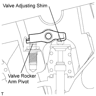
Make sure that the 32 No. 1 valve rocker arm subassembly are installed as shown in the illustration.
-
-
INSTALL FUEL INJECTOR ASSEMBLY (for Direct Injection)
-
INSTALL NO. 3 CAMSHAFT
-
INSTALL NO. 4 CAMSHAFT
-
INSTALL CAMSHAFT
-
INSTALL NO. 2 CAMSHAFT
-
INSTALL EXHAUST MANIFOLD SUB-ASSEMBLY LH
-
INSTALL EXHAUST MANIFOLD SUB-ASSEMBLY RH
-
INSTALL ENGINE AND TRANSMISSION