CAMSHAFT INSTALLATION

-
INSTALL NO. 3 CAMSHAFT
-
Apply a light coat of engine oil to the camshaft journals.
-
Install the No. 3 camshaft to the cylinder head sub-assembly.
-
-
INSTALL NO. 4 CAMSHAFT
-
Apply a light coat of engine oil to the camshaft journals.
-
Install the No. 4 camshaft to the cylinder head sub-assembly.
-
-
INSTALL CAMSHAFT BEARING CAP (for Bank 1)
Note
When rotating the camshafts without the timing chains installed, be careful to ensure that the valves do not contact the pistons. If contact occurs between the valves and pistons, damage may result.
-
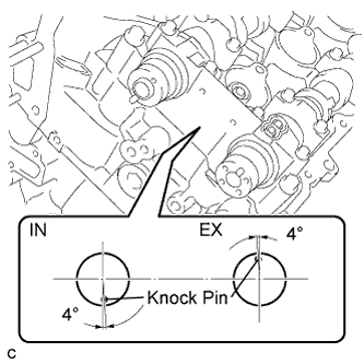
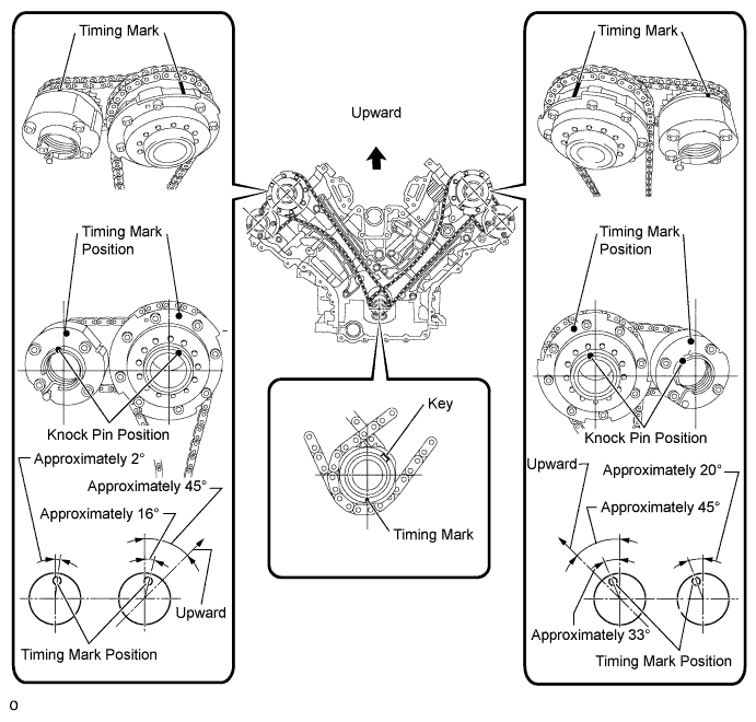
Make sure that each knock pin of the camshafts is positioned as shown in the illustration.
-
Apply a light coat of engine oil to the camshaft housing and bearing caps.
-
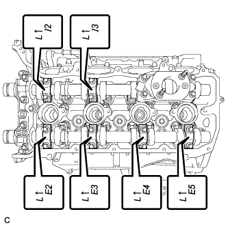
Confirm the marks and numbers on the camshaft bearing caps and place them in their proper positions and directions.
-
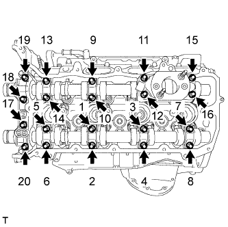
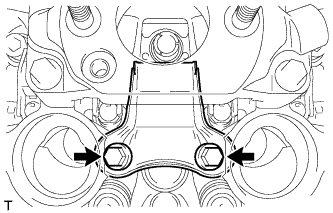
Temporarily install the 20 bolts in the sequence shown in the illustration.
- Torque:
- 10 N*m { 102 kgf*cm, 7 ft.*lbf }
-
Tighten the 20 bolts in the sequence shown in the illustration.
- Torque:
- 19 N*m { 190 kgf*cm, 14 ft.*lbf }
-
-
INSTALL CAMSHAFT
-
Apply a light coat of engine oil to the camshaft journals.
-
Install the camshaft to the cylinder head sub-assembly.
-
-
INSTALL NO. 2 CAMSHAFT
-
Apply a light coat of engine oil to the camshaft journals.
-
Install the No. 2 camshaft to the cylinder head sub-assembly.
-
-
INSTALL CAMSHAFT BEARING CAP (for Bank 2)
Note
When rotating the camshafts without the timing chains installed, be careful to ensure that the valves do not contact the pistons. If contact occurs between the valves and pistons, damage may result.
-
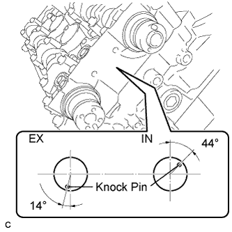
Make sure that each knock pin of the camshafts is positioned as shown in the illustration.
-
Apply a light coat of engine oil to the camshaft housing and bearing caps.
-
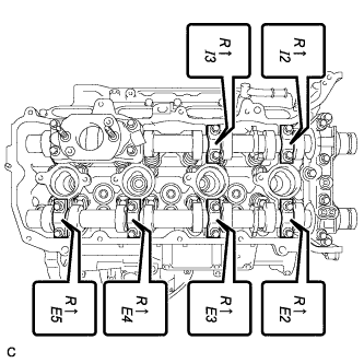
Confirm the marks and numbers on the camshaft bearing caps and place them in their proper positions and directions.
-
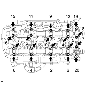
Temporarily install the 20 bolts in the sequence shown in the illustration.
- Torque:
- 10 N*m { 102 kgf*cm, 7 ft.*lbf }
-
Tighten the 20 bolts in the sequence shown in the illustration.
- Torque:
- 19 N*m { 190 kgf*cm, 14 ft.*lbf }
-
-
INSTALL NO. 2 CHAIN TENSIONER ASSEMBLY
-
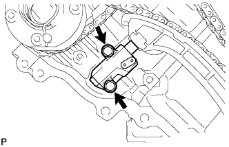
Install the No. 2 chain tensioner assembly with the 2 bolts.
- Torque:
- 10 N*m { 102 kgf*cm, 7 ft.*lbf }
-
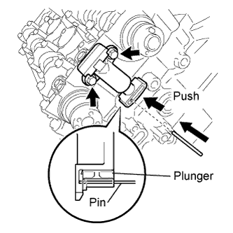
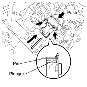
While raising the No. 2 chain tensioner assembly, insert a 1.0 mm (0.0394 in.) pin into the hole to fix it in place.
-
-
INSTALL CHAIN SUB-ASSEMBLY (for Bank 2)
Tech Tips
The crankshaft timing gear, camshaft timing gear assembly and camshaft timing exhaust gear assembly will be installed with the chain sub-assembly and No. 2 chain sub-assembly connected to the gears.
-
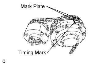
Align the chain's orange mark plates with the camshaft timing gear's timing mark, and attach the chain sub-assembly to the gear as shown in the illustration.
-
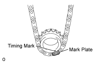
Align the chain's orange mark plate with the crankshaft timing gear's timing mark, and attach the chain sub-assembly to the gear as shown in the illustration.
-
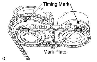
Align the No. 2 chain's mark plates (yellow) with the timing marks of the camshaft timing gear assembly and camshaft timing exhaust gear assembly, and attach the No. 2 chain sub-assembly to the gears as shown in the illustration.
-
Install the crankshaft timing gear to the crankshaft.
-
Align and attach the knock pin of the camshaft with the pin hole of the camshaft timing gear assembly.
-
Using the hexagonal portion of the No. 2 camshaft, align and attach the knock pin of the No. 2 camshaft with the pin hole of the camshaft timing exhaust gear assembly.
-
Remove the pin from the No. 2 chain tensioner.
-
-
INSTALL NO. 1 CHAIN VIBRATION DAMPER (for Bank 2)
-
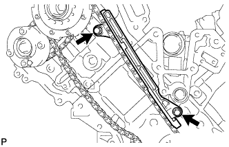
Install the No. 1 chain vibration damper with the 2 bolts.
- Torque:
- 21 N*m { 214 kgf*cm, 15 ft.*lbf }
-
-
INSTALL CHAIN TENSIONER SLIPPER (for Bank 2)
-
Install the chain tensioner slipper.
Tech Tips
If you cannot install the chain tensioner slipper due to the tension of the chain, use the hexagonal portion of the camshaft to loosen the chain, and then install the chain tensioner slipper.
-
-
INSTALL NO. 1 CHAIN TENSIONER ASSEMBLY (for Bank 2)
-
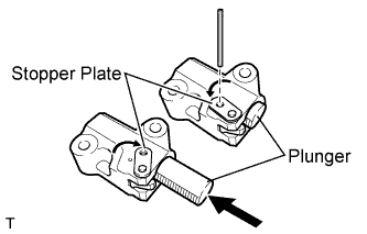
Move the stopper plate upward to release the lock, and fully push the plunger into the No. 1 chain tensioner assembly.
-
Move the stopper plate downward to set the lock, and insert a 2 mm hexagon wrench into the hole of the stopper plate.
-
Install the No. 1 chain tensioner assembly with the 2 bolts.
- Torque:
- 10 N*m { 102 kgf*cm, 7 ft.*lbf }
-
Remove the hexagon wrench from the No. 1 chain tensioner assembly.
-
-
INSTALL NO. 3 CHAIN TENSIONER ASSEMBLY (for Bank 1)
-
Install the No. 3 chain tensioner assembly with the 2 bolts.
- Torque:
- 10 N*m { 102 kgf*cm, 7 ft.*lbf }
-
While raising the No. 3 chain tensioner assembly, insert a 1.0 mm (0.0394 in.) pin into the hole to fix it in place.
-
-
INSTALL CHAIN SUB-ASSEMBLY (for Bank 1)
Tech Tips
The crankshaft timing sprocket LH, camshaft timing gear assembly and camshaft timing exhaust gear assembly will be installed with the chain sub-assembly and No. 2 chain sub-assembly connected to the gears.
-

Align the chain's orange mark plates with the camshaft timing gear's timing mark, and attach the chain sub-assembly to the gear as shown in the illustration.
-
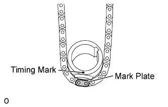
Align the chain's orange mark plate with the crankshaft timing sprocket's timing mark, and attach the chain sub-assembly to the gear as shown in the illustration.
-
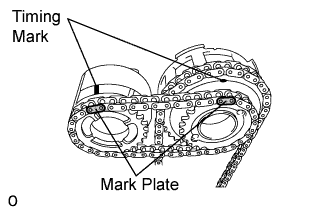
Align the No. 2 chain's mark plates (yellow) with the timing marks of the camshaft timing gear assembly and camshaft timing exhaust gear assembly, and attach the No. 2 chain sub-assembly to the gears as shown in the illustration.
-
Install the crankshaft timing sprocket LH to the crankshaft.
-
Align and attach the knock pin of the No. 3 camshaft with the pin hole of the camshaft timing gear assembly.
-
Using the hexagonal portion of the No. 4 camshaft, align and attach the knock pin of the No. 4 camshaft with the pin hole of the camshaft timing exhaust gear assembly.
Note
Because the gears' timing mark positions may shift due to looseness of the chain sub-assembly, use the hexagonal portion of the camshaft to hold the No. 3 camshaft in place until the No. 1 chain tensioner assembly is installed.
-
Remove the pin from the No. 2 chain tensioner assembly.
-
-
INSTALL NO. 1 CHAIN VIBRATION DAMPER (for Bank 1)
-
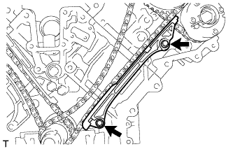
Install the No. 1 chain vibration damper with the 2 bolts.
- Torque:
- 21 N*m { 214 kgf*cm, 15 ft.*lbf }
-
Remove the hexagon wrench from the No. 1 chain tensioner assembly.
-
-
INSTALL CHAIN TENSIONER SLIPPER (for Bank 1)
-
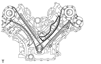
Install the chain tensioner slipper.
Tech Tips
If you cannot install the chain tensioner slipper due to the tension of the chain, use the hexagonal portion of the camshaft to loosen the chain and install the chain tensioner slipper.
-
-
INSTALL NO. 1 CHAIN TENSIONER ASSEMBLY (for Bank 1)
-
Move the stopper plate upward to release the lock, and fully push the plunger into the No. 1 chain tensioner assembly.
-
Move the stopper plate downward to set the lock, and insert a 2 mm hexagon wrench into the hole of the stopper plate.
-
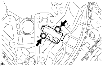
Install the No. 1 chain tensioner assembly and chain tensioner gasket with the 2 bolts.
- Torque:
- 10 N*m { 102 kgf*cm, 7 ft.*lbf }
-
-
TIGHTEN CAMSHAFT TIMING GEAR ASSEMBLY
-
for Bank 1:
-
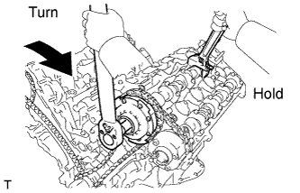
Using a wrench, hold the hexagonal portion of the No. 3 camshaft.
-
Using a 12 mm socket hexagon wrench, tighten the camshaft timing gear assembly with a new bolt.
- Torque:
- 79 N*m { 806 kgf*cm, 58 ft.*lbf }
-
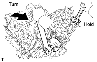
Using a wrench to hold the hexagonal portion of the No. 4 camshaft, tighten the camshaft timing exhaust gear assembly with the bolt.
- Torque:
- 100 N*m { 1020 kgf*cm, 74 ft.*lbf }
-
-
for Bank 2:
-
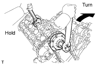
Using a wrench, hold the hexagonal portion of the No. 1 camshaft.
-
Using a 12 mm socket hexagon wrench, tighten the camshaft timing gear assembly with a new bolt.
- Torque:
- 79 N*m { 806 kgf*cm, 58 ft.*lbf }
-
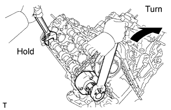
Using a wrench to hold the hexagonal portion of the No. 2 camshaft, tighten the camshaft timing exhaust gear assembly with the bolt.
- Torque:
- 100 N*m { 1020 kgf*cm, 74 ft.*lbf }
-
-
-
INSPECT NO. 1 CYLINDER TO TDC/COMPRESSION
-
Temporarily install the crankshaft pulley set bolt.
-
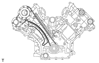
Rotate the crankshaft clockwise, and check that the timing marks on the crankshaft timing gear and camshaft timing gears are as shown in the illustration.
-
Remove the crankshaft pulley set bolt.
-
-
INSPECT VALVE CLEARANCE
-
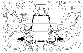
Using a feeler gauge, measure the clearance between the indicated valve rocker arms and camshafts.
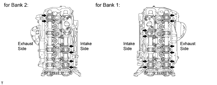
Standard Valve Clearance (Cold) Item Specified Condition Intake 0.12 to 0.18 mm (0.00472 to 0.00709 in.) Exhaust 0.22 to 0.28 mm (0.00866 to 0.0110 in.) Tech Tips
-
On this engine, valve clearance is measured between the valve rocker arms and the camshaft lobes. The shims used to adjust the valve clearance are located on the top of the valve stems.
-
The valve clearance shown in the Standard Valve Clearance table is the clearance as measured between the cam lobe and valve rocker arm.
-
Record any out-of-specification valve clearance measurements. They will be used later to determine the required replacement valve adjusting shim.
-
-
Turn the crankshaft 1 revolution (360°) to set the No. 6 cylinder to TDC compression.
-
Using a feeler gauge, measure the clearance between the indicated valve rocker arms and camshafts.
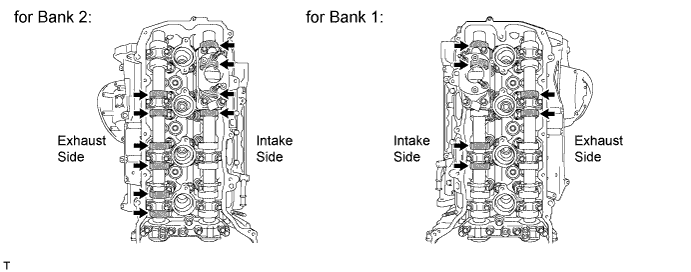
Standard Valve Clearance (Cold) Item Specified Condition Intake 0.12 to 0.18 mm (0.00472 to 0.00709 in.) Exhaust 0.22 to 0.28 mm (0.00866 to 0.0110 in.) Tech Tips
-
On this engine, valve clearance is measured between the valve rocker arms and the camshaft lobes. The shims used to adjust the valve clearance are located on the top of the valve stems.
-
The valve clearance shown in the Standard Valve Clearance table is the clearance as measured between the cam lobe and valve rocker arm.
-
Record any out-of-specification valve clearance measurements. They will be used later to determine the required replacement valve adjusting shim.
-
-
-
ADJUST VALVE CLEARANCE
-
Remove the timing chain cover sub-assembly Click here.
-
Remove the camshaft Click here.
-
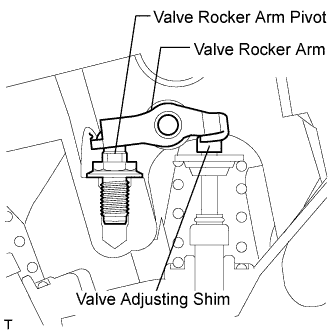
Raise the valve rocker arm above the shim being replaced, and remove the valve adjusting shim.
Note
-
Be careful not to drop the adjusting shim into the cylinder head.
-
To prevent damage, do not attempt to adjust valve clearance by tightening or loosening the valve rocker arm pivots.
Tech Tips
Arrange the removed parts in the correct order.
-
-
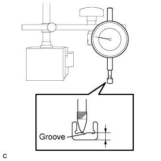
Using a dial gauge, measure the thickness of the existing valve adjusting shim after removing it.
Tech Tips
Be careful not to measure at the valve adjusting shim center groove.
-
Determine the replacement valve adjusting shim thickness according to the formula or charts below.
-
Calculate the thickness of the replacement valve adjusting shim so that the valve clearance comes within the specified value.
T2 Thickness of replacement shim T1 Thickness of existing shim A Measured valve clearance Valve clearance Intake T2 = T1 + (A - 0.15 mm (0.0059 in.)) x 1.8 Exhaust T2 = T1 + (A - 0.25 mm (0.0098 in.)) x 1.6 This example is provided only as a calculation example, based on the clearance adjustment of an intake valve. If non-metric units are being used, substitute those measurements for the values shown below.
Step 1 - Determining the amount of excess clearance
-
The specified clearance (0.15) is subtracted from the measured value (0.40), and the result is then multiplied by the rocker ratio compensation value (1.8).
-
(Measured value - specification) x compensation value = amount of excess clearance
-
(0.40 - 0.15) x 1.8 = 0.450
Step 2 - Using the existing valve adjusting shim to determine the required thickness of the replacement valve adjusting shim
-
The amount of excess clearance (0.450) is added to the thickness of the existing valve adjusting shim (2.300). The resulting value is the ideal thickness of a replacement valve adjusting shim.
-
Excess clearance + thickness of existing shim = thickness of ideal replacement shim
-
0.450 + 2.300 = 2.750
Step 3 - Select the valve adjusting shim closest to the thickness of the ideal replacement shim
-
Compare the thickness of the available replacement valve adjusting shims to the ideal replacement shim and choose the shim that is the closest match.
-
Closest replacement valve adjusting shim = 2.750 (Select a new No. 74 shim.)
Tech Tips
-
Select a replacement shim with a thickness as close to the calculated value as possible.
-
Shims are available in 41 sizes in increments of 0.020 mm (0.0008 in.), from 2.000 mm (0.0787 in.) to 2.800 mm (0.1102 in.).
-
To select a replacement valve adjusting shim, refer to the following Valve Adjusting Shim Selection Chart and New Shim Thickness tables.
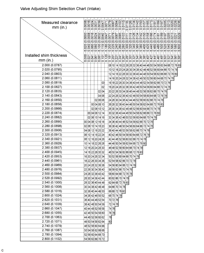
Intake valve clearance (Cold) 0.12 to 0.18 mm (0.00472 to 0.00709 in.) EXAMPLE:
If the existing shim (installed shim) is 2.300 mm (0.0906 in.), and the measured clearance is 0.39 mm (0.0154 in.), then a new 2.740 mm (0.1079 in.) No. 74 shim should be used as a replacement for the existing shim.
New Shim Thickness mm (in.) Shim No. Thickness Shim No. Thickness Shim No. Thickness 00 2.000 (0.0787) 28 2.280 (0.0898) 56 2.560 (0.1008) 02 2.020 (0.0795) 30 2.300 (0.0906) 58 2.580 (0.1016) 04 2.040 (0.0803) 32 2.320 (0.0913) 60 2.600 (0.1024) 06 2.060 (0.0811) 34 2.340 (0.0921) 62 2.620 (0.1031) 08 2.080 (0.0819) 36 2.360 (0.0929) 64 2.640 (0.1039) 10 2.100 (0.0827) 38 2.380 (0.0937) 66 2.660 (0.1047) 12 2.120 (0.0835) 40 2.400 (0.0945) 68 2.680 (0.1055) 14 2.140 (0.0843) 42 2.420 (0.0953) 70 2.700 (0.1063) 16 2.160 (0.0850) 44 2.440 (0.0961) 72 2.720 (0.1071) 18 2.180 (0.0858) 46 2.460 (0.0969) 74 2.740 (0.1079) 20 2.200 (0.0866) 48 2.480 (0.0976) 76 2.760 (0.1087) 22 2.220 (0.0874) 50 2.500 (0.0984) 78 2.780 (0.1094) 24 2.240 (0.0882) 52 2.520 (0.0992) 80 2.800 (0.1102) 26 2.260 (0.0890) 54 2.540 (0.1000) 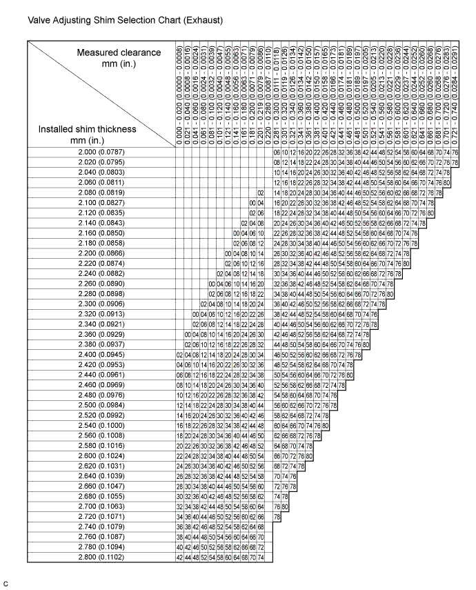
Exhaust valve clearance (Cold) 0.22 to 0.28 mm (0.00866 to 0.0110 in.) EXAMPLE:
If the existing shim (installed shim) is 2.300 mm (0.0906 in.), and the measured clearance is 0.39 mm (0.0154 in.), then a new 2.520 mm (0.0992 in.) No. 52 shim should be used as a replacement for the existing shim.
New Shim Thickness mm (in.) Shim No. Thickness Shim No. Thickness Shim No. Thickness 00 2.000 (0.0787) 28 2.280 (0.0898) 56 2.560 (0.1008) 02 2.020 (0.0795) 30 2.300 (0.0906) 58 2.580 (0.1016) 04 2.040 (0.0803) 32 2.320 (0.0913) 60 2.600 (0.1024) 06 2.060 (0.0811) 34 2.340 (0.0921) 62 2.620 (0.1031) 08 2.080 (0.0819) 36 2.360 (0.0929) 64 2.640 (0.1039) 10 2.100 (0.0827) 38 2.380 (0.0937) 66 2.660 (0.1047) 12 2.120 (0.0835) 40 2.400 (0.0945) 68 2.680 (0.1055) 14 2.140 (0.0843) 42 2.420 (0.0953) 70 2.700 (0.1063) 16 2.160 (0.0850) 44 2.440 (0.0961) 72 2.720 (0.1071) 18 2.180 (0.0858) 46 2.460 (0.0969) 74 2.740 (0.1079) 20 2.200 (0.0866) 48 2.480 (0.0976) 76 2.760 (0.1087) 22 2.220 (0.0874) 50 2.500 (0.0984) 78 2.780 (0.1094) 24 2.240 (0.0882) 52 2.520 (0.0992) 80 2.800 (0.1102) 26 2.260 (0.0890) 54 2.540 (0.1000) -
-
-
Install the camshaft Click here.
-
Install the chain sub-assembly Click here.
-
Install the chain sub-assembly (for Bank 2).
-
Install the No. 1 chain vibration damper (for Bank 2).
-
Install the chain tensioner slipper (for Bank 2).
-
Install the No. 1 chain tensioner assembly (for Bank 2).
-
Install the chain sub-assembly (for Bank 1).
-
Install the No. 1 chain vibration damper (for Bank 1).
-
Install the chain tensioner slipper (for Bank 1).
-
Install the No. 1 chain tensioner assembly (for Bank 1).
-
Tighten the camshaft timing gear assembly.
-
-
Inspect the valve clearance again.
Note
Be sure to inspect the valve clearance with the chain cub-assembly installed. When rotating the camshaft without the chain sub-assembly installed, contact between the valves and pistons may occur.
Tech Tips
If the valve clearance is not as specified, readjust the valve clearance.
-
-
INSTALL OIL REFLECTOR PLATE LH (for Bank 1)
-
Install the oil reflector plate LH with the 2 bolts.
- Torque:
- 10 N*m { 102 kgf*cm, 7 ft.*lbf }
-
-
INSTALL OIL REFLECTOR PLATE RH (for Bank 2)
-
Install the oil reflector plate RH with the 2 bolts.
- Torque:
- 10 N*m { 102 kgf*cm, 7 ft.*lbf }
-
-
INSTALL TIMING CHAIN COVER SUB-ASSEMBLY