ENGINE UNIT INSPECTION

-
INSPECT CAMSHAFT TIMING EXHAUST GEAR ASSEMBLY
-

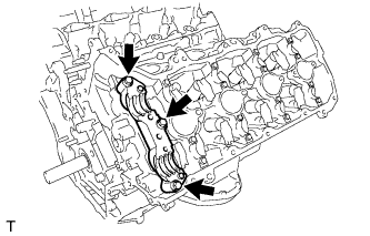
Install the camshaft housing to the cylinder head sub-assembly LH (for Bank 1).
-
Place the camshaft housing onto the cylinder head sub-assembly LH.
-
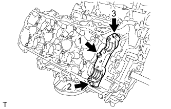
Temporarily tighten the camshaft housing with the 3 bolts in the sequence shown in the illustration.
- Torque:
- 10 N*m { 102 kgf*cm, 7 ft.*lbf }
-
Fully tighten the 3 bolts in the sequence shown in the illustration.
- Torque:
- 24 N*m { 245 kgf*cm, 18 ft.*lbf }
-
-
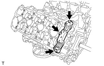
Install the camshaft housing to the cylinder head sub-assembly (for Bank 2).
-
Place the camshaft housing onto the cylinder head sub-assembly.
-
Temporarily tighten the camshaft housing with the 3 bolts in the sequence shown in the illustration.
- Torque:
- 10 N*m { 102 kgf*cm, 7 ft.*lbf }
-
Fully tighten the 3 bolts in the sequence shown in the illustration.
- Torque:
- 24 N*m { 245 kgf*cm, 18 ft.*lbf }
-
-
Install the No. 4 camshaft.
Tech Tips
Only install the exhaust camshaft.
-
Install the No. 2 camshaft.
Tech Tips
Only install the exhaust camshaft.
-
Install the camshaft bearing cap (for Bank 1) Click here.
-
Install the camshaft bearing cap (for Bank 2) Click here.
-
Apply a light coat of engine oil to the camshaft and camshaft timing exhaust gear assembly.
-
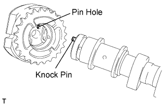
Align and insert the knock pin of the camshaft into the pin hole of the camshaft timing exhaust gear assembly.
Note
-
Do not forcefully push in the camshaft timing exhaust gear assembly. This may cause the camshaft knock pin tip to damage the camshaft timing exhaust gear assembly.
-
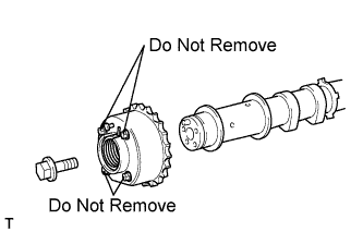
Be sure not to remove the other 4 bolts. If removed, replace the camshaft timing exhaust gear assembly.
-
-
Apply a light coat of engine oil to the threads and under the head of the bolt.
-
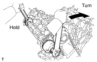
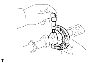
Using a wrench to hold the hexagonal portion of the camshaft, install the camshaft timing exhaust gear assembly with the bolt.
- Torque:
- 100 N*m { 1020 kgf*cm, 74 ft.*lbf }
-
Remove the camshaft bearing cap (for Bank 1) Click here.
-
Remove the camshaft bearing cap (for Bank 2) Click here.
-
Check the lock of the camshaft timing exhaust gear assembly.
-
Make sure that the camshaft timing exhaust gear assembly is locked.
-
-
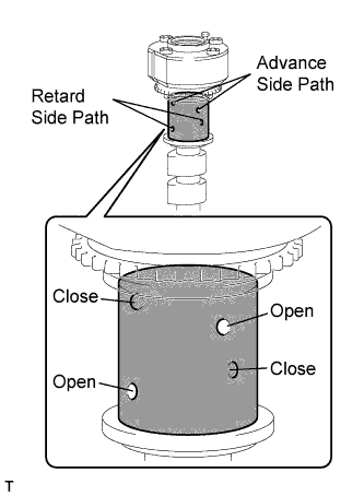
Release the lock pin.
-
Cover the 4 oil paths of the cam journal with vinyl tape as shown in the illustration.
-
Prick a hole in the tape placed on the advance side path. Prick a hole in the tape placed on the retard side path on the opposite side to that of the advance side path, as shown in the illustration.
-
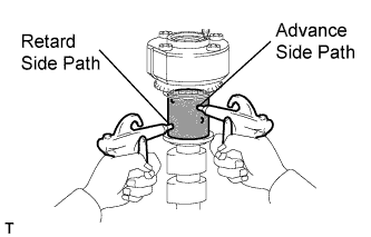
Apply approximately 200 kPa (2.0 kgf/cm2, 28 psi) of air pressure to the 2 broken paths (the advance side path and the retard side path).
CAUTION:
Cover the paths with a piece of cloth when applying pressure to keep oil from splashing.
-
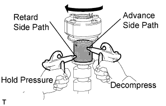
Check that the camshaft timing exhaust gear assembly rotates in the retard direction when reducing the air pressure applied to the advance side path.
Tech Tips
This operation releases the lock pin for the most retarded position.
-
When the camshaft timing exhaust gear assembly reaches the most retarded position, release the air pressure from the advance side path and retard side path, in that order.
Note
Do not release the air pressure from the retard side path first. The gear may abruptly shift in the advance direction and break the lock pin.
-
-
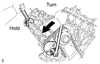
Check for smooth rotation.
-
Turn the camshaft timing exhaust gear assembly within its movable range (21°) 2 or 3 times, but do not turn it to the most advanced position. Make sure that the gear turns smoothly.
Note
Do not use air pressure to check for smooth rotation.
-
-
Check the lock in the most advanced position.
-
Confirm that the camshaft timing exhaust gear assembly is locked at the most advanced position.
-
-
Install the No. 4 camshaft.
Tech Tips
Only install the exhaust camshaft.
-
Install the No. 2 camshaft.
Tech Tips
Only install the exhaust camshaft.
-
Install the camshaft bearing cap (for Bank 1) Click here.
-
Install the camshaft bearing cap (for Bank 2) Click here.
-
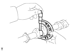
Hold the hexagonal portion of the camshaft with a wrench and loosen the bolt.
-
Remove the camshaft bearing cap (for Bank 1) Click here.
-
Remove the camshaft bearing cap (for Bank 2) Click here.
-
Remove the flange bolt and camshaft timing exhaust gear assembly.
Note
Be sure not to remove the other 4 bolts.
-
Remove the camshaft housing from the cylinder head sub-assembly LH (for Bank 1).
-
Remove the 3 bolts and camshaft housing from the cylinder head sub-assembly LH.
-
-
Remove the camshaft housing from the cylinder head sub-assembly (for Bank 2).
-
Remove the 3 bolts and camshaft housing from the cylinder head sub-assembly.
-
-
-
INSPECT NO. 1 VALVE ROCKER ARM SUB-ASSEMBLY
-
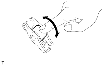
Turn the roller by hand to check that it turns smoothly.
If the roller does not turn smoothly, replace the No. 1 valve rocker arm sub-assembly.
-
-
INSPECT CAMSHAFT
-
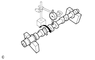
Inspect the camshaft for runout.
-
Place the camshaft on V-blocks.
-
Using a dial indicator, measure the circle runout at the center journal.
Maximum circle runout 0.04 mm (0.00157 in.) If the circle runout is greater than the maximum, replace the camshaft.
Tech Tips
Check the oil clearance after replacing the camshaft.
-
-
Using a micrometer, measure the cam lobe height.
Standard Cam Lobe Height Item Specified Condition Intake 44.953 to 45.103 mm (1.7698 to 1.7757 in.) Exhaust 44.576 to 44.726 mm (1.7549 to 1.7609 in.) Minimum Cam Lobe Height Item Specified Condition Intake 44.903 mm (1.7678 in.) Exhaust 44.526 mm (1.7530 in.) If the cam lobe height is less than the minimum, replace the camshaft.
-
Using a micrometer, measure the journal diameter.
Standard Journal Diameter Item Specified Condition No. 1 journal 29.956 to 29.970 mm (1.1794 to 1.1799 in.) Other journal 25.959 to 25.975 mm (1.0220 to 1.0226 in.) If the journal diameter is not as specified, check the oil clearance.
-
-
INSPECT CAMSHAFT OIL CLEARANCE
-
Clean the bearing caps, camshaft housing and camshaft journals.
-
Install the camshaft housing onto the cylinder head sub-assembly LH (for Bank 1).
-
Place the camshaft housing to the cylinder head sub-assembly LH.
-
Temporarily tighten the camshaft housing with the 3 bolts in the sequence shown in the illustration.
- Torque:
- 10 N*m { 102 kgf*cm, 7 ft.*lbf }
-
Fully tighten the 3 bolts in the sequence shown in the illustration.
- Torque:
- 24 N*m { 245 kgf*cm, 18 ft.*lbf }
-
-
Install the camshaft housing to the cylinder head sub-assembly (for bank 2).
-
Place the camshaft housing onto the cylinder head sub-assembly.
-
Temporarily tighten the camshaft housing with the 3 bolts in the sequence shown in the illustration.
- Torque:
- 10 N*m { 102 kgf*cm, 7 ft.*lbf }
-
Fully tighten the 3 bolts in the sequence shown in the illustration.
- Torque:
- 24 N*m { 245 kgf*cm, 18 ft.*lbf }
-
-
Place the camshafts on the cylinder heads.
-
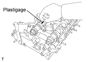
Lay a strip of Plastigage across each of the camshaft journals.
-
Install the camshaft bearing cap (for Bank 1) Click here.
Note
Do not turn the camshaft.
-
Install the camshaft bearing cap (for Bank 2) Click here.
Note
Do not turn the camshaft.
-
Remove the camshaft bearing cap (for Bank 1) Click here.
-
Remove the camshaft bearing cap (for Bank 2) Click here.
-
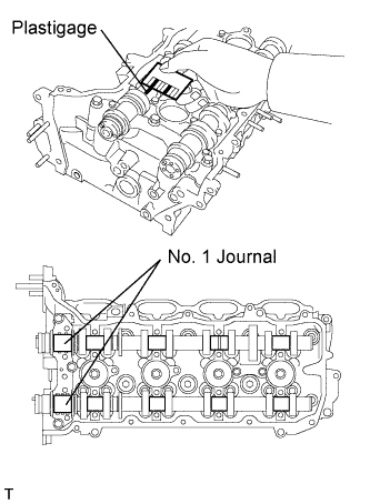
Measure the Plastigage at its widest point.
Standard Oil Clearance Item Specified Condition No. 1 journal 0.030 to 0.069 mm (0.00118 to 0.00272 in.) Other journal 0.025 to 0.062 mm (0.000984 to 0.00244 in.) Maximum Oil Clearance Item Specified Condition No. 1 journal 0.09 mm (0.00354 in.) Other journal 0.09 mm (0.00354 in.) If the oil clearance is greater than the maximum, replace the camshaft. If necessary, replace the cylinder head sub-assembly.
-
Remove the camshafts from the cylinder heads.
-
Remove the camshaft housing from the cylinder head sub-assembly LH (for Bank 1).
-
Remove the 3 bolts and camshaft housing from the cylinder head sub-assembly LH.
-
-
Remove the camshaft housing from the cylinder head sub-assembly (for Bank 2).
-
Remove the 3 bolts and camshaft housing from the cylinder head sub-assembly.
-
-
-
INSPECT CAMSHAFT TIMING GEAR ASSEMBLY
-
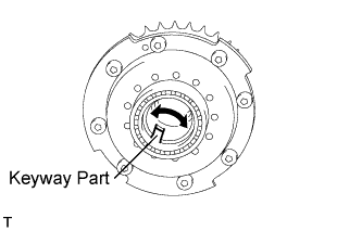
Using a vernier caliper, measure the width of the camshaft timing gear assembly's eccentric shaft cutout.
Standard width 5.9 to 6.2 mm (0.232 to 0.244 in.) Maximum width 6.7 mm (0.264 in.) If the result is greater than the maximum value, replace the camshaft timing gear assembly.
-
Rotate the keyway part of the camshaft timing gear assembly's eccentric shaft by hand.
Standard Rotates smoothly If the result is not as specified, replace the camshaft timing gear assembly.
Note
-
Do not drop the camshaft timing gear assembly. If dropped, replace it.
-
Do not disassemble the camshaft timing gear assembly. If disassembled, replace it.
-
-
-
INSPECT CYLINDER HEAD SET BOLT
-
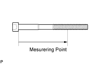
Using a vernier caliper, measure the minimum diameter of the elongated thread at the measuring point.
Standard outside diameter 10.85 to 11.00 mm (0.427 to 0.433 in.) Minimum outside diameter 10.6 mm (0.417 in.) Measuring point 90 mm (3.54 in.) for intake side bolt 85 mm (3.35 in.) for exhaust side bolt Tech Tips
-
If a visual check shows no excessively thin areas, check the center of the bolt (see illustration) and find the area that has the smallest diameter.
-
If the diameter is less than the minimum, replace the cylinder head set bolt.
-
-
-
INSPECT CHAIN SUB-ASSEMBLY
-
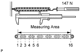
Using a spring scale, pull the chain sub-assembly with a force of 147 N (15 kgf, 33 lbf) as shown in the illustration.
-
Using a vernier caliper, measure the length of 15 pins.
Maximum chain elongation 136.9 mm (5.39 in.) If the elongation is greater than the maximum, replace the chain sub-assembly.
Note
Perform the measurement at 3 random places.
-
-
INSPECT NO. 2 CHAIN SUB-ASSEMBLY
-
Using a spring scale, pull the No. 2 chain subassembly with a force of 147 N (15 kgf, 33 lbf) as shown in the illustration.
-
Using a vernier caliper, measure the length of 15 pins.
Maximum chain elongation 137.6 mm (5.42 in.) If the elongation is greater than the maximum, replace the No. 2 chain sub-assembly.
Note
Perform the measurement at 3 random places.
-
-
INSPECT CRANKSHAFT TIMING GEAR
-
Wrap the chain sub-assembly around the sprocket.
-
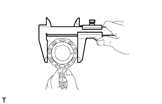
Using a vernier caliper, measure the sprocket diameter with the chain sub-assembly.
Minimum sprocket diameter (w/ chain subassembly) 61.4 mm (2.42 in.) Tech Tips
The vernier caliper must contact the chain sub-assembly rollers for the measurement.
If the diameter is less than the minimum, replace the chain sub-assembly and crankshaft timing gear.
-
-
INSPECT CRANKSHAFT TIMING SPROCKET LH
-

Wrap the chain sub-assembly around the crankshaft timing sprocket LH.
-
Using a vernier caliper, measure the crankshaft timing sprocket LH diameter with the chain sub-assembly.
Minimum crankshaft timing sprocket LH diameter (w/ chain sub-assembly) 61.4 mm (2.42 in.) Note
The vernier caliper must contact the chain sub-assembly rollers for the measurement.
If the diameter is less than the minimum, replace the chain sub-assembly and crankshaft timing sprocket LH.
-
-
INSPECT NO. 1 CHAIN TENSIONER ASSEMBLY
-
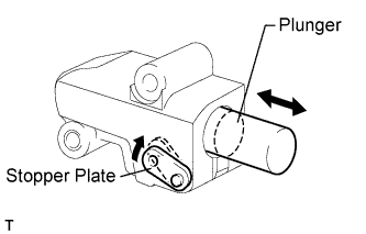
Move the stopper plate upward to release the lock. Push the plunger and check that it moves smoothly.
If necessary, replace the No. 1 chain tensioner assembly.
-
-
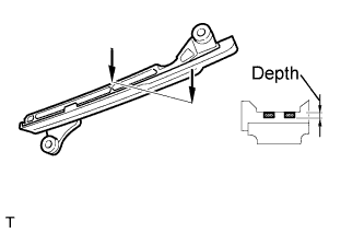
INSPECT NO. 2 CHAIN TENSIONER ASSEMBLY
-
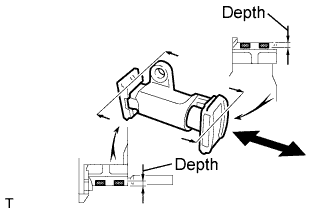
Check that the plunger moves smoothly.
-
Measure the worn depth of the No. 2 chain tensioner assembly.
Maximum depth 0.9 mm (0.0354 in.) If the depth is greater than the maximum, replace the No. 2 chain tensioner assembly.
-
-
INSPECT NO. 3 CHAIN TENSIONER ASSEMBLY
-
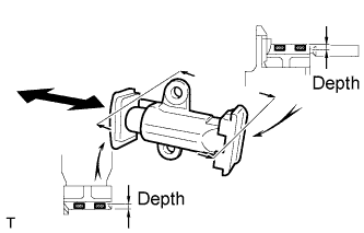
Check that the plunger moves smoothly.
-
Measure the worn depth of the No. 3 chain tensioner assembly.
Maximum depth 0.9 mm (0.0354 in.) If the depth is greater than the maximum, replace the No. 3 chain tensioner assembly.
-
-
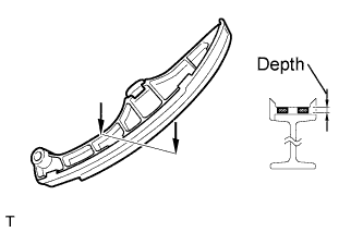
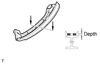
INSPECT CHAIN TENSIONER SLIPPER
-
for Bank 1:
-
Measure the worn depth of the chain tensioner slipper.
Maximum depth 1.0 mm (0.0394 in.) If the depth is greater than the maximum, replace the chain tensioner slipper.
-
-
for Bank 2:
-
Measure the worn depth of the chain tensioner slipper.
Maximum depth 1.0 mm (0.0394 in.) If the depth is greater than the maximum, replace the chain tensioner slipper.
-
-
-
INSPECT NO. 1 CHAIN VIBRATION DAMPER
-
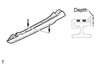
for Bank 1:
-
Measure the worn depth of the No. 1 chain vibration damper.
Maximum depth 1.0 mm (0.0394 in.) If the depth is greater than the maximum, replace the No. 1 chain vibration damper.
-
-
for Bank 2:
-
Measure the worn depth of the No. 1 chain vibration damper.
Maximum depth 1.0 mm (0.0394 in.) If the depth is greater than the maximum, replace the No. 1 chain vibration damper.
-
-
-
INSPECT CYLINDER HEAD SUB-ASSEMBLY
-
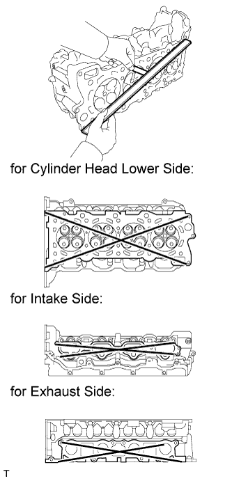
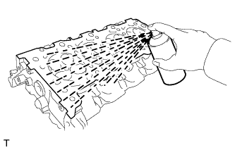
Using a precision straightedge and feeler gauge, measure the warpage of the contact surfaces of the cylinder block and manifold.
Standard Warpage Item Specified Condition Cylinder head lower side 0.05 mm (0.00197 in.) Intake side 0.08 mm (0.00315 in.) Exhaust side 0.05 mm (0.00197 in.) Maximum warpage 0.10 mm (0.00394 in.) If the warpage is greater than the maximum, replace the cylinder head.
-
Using a dye penetrant, check the intake ports, exhaust ports and cylinder surface for cracks.
If cracked, replace the cylinder head.
-
-
INSPECT EXHAUST MANIFOLD SUB-ASSEMBLY LH
-
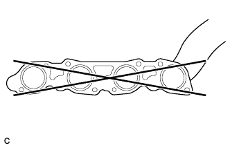
Using a precision straightedge and feeler gauge, measure the warpage of the surface that contacts the cylinder head sub-assembly LH (for Bank 1).
Maximum warpage 0.5 mm (0.0197 in.) If the warpage is greater than the maximum, replace the exhaust manifold sub-assembly LH.
-
-
INSPECT EXHAUST MANIFOLD SUB-ASSEMBLY RH
-
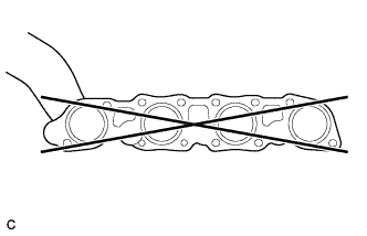
Using a precision straightedge and feeler gauge, measure the warpage of the surface that contacts the cylinder head sub-assembly RH.
Maximum warpage 0.5 mm (0.0197 in.) If the warpage is greater than the maximum, replace the exhaust manifold sub-assembly RH.
-