RELAY ON-VEHICLE INSPECTION

-
DISCONNECT CABLE FROM NEGATIVE BATTERY TERMINAL
CAUTION:
Wait at least 90 seconds after disconnecting the cable from the negative (-) battery terminal to disable the SRS system.
Note
When disconnecting the cable, some systems need to be initialized after the cable is reconnected Click here.
-
REMOVE COOL AIR INTAKE DUCT SEAL
-
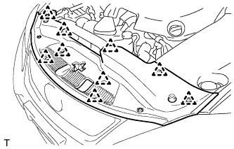
Remove the 9 clips and cool air intake duct seal.
-
-
REMOVE ENGINE ROOM SIDE COVER LH (for LHD)
-

Remove the 5 clips and engine room side cover LH.
-
-
REMOVE ENGINE ROOM SIDE COVER LH (for RHD)
-
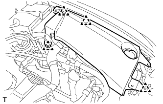
Remove the 4 clips and engine room side cover LH.
-
-
REMOVE NO. 2 RELAY BLOCK COVER
-
INSPECT IG2 RELAY
-
Remove the IG2 relay from the No. 2 relay block.
-
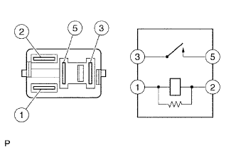
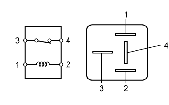
Measure the resistance according to the value(s) in the table below.
Standard Resistance Tester Connection Condition Specified Condition 3 - 5 No battery voltage is applied across terminals 1 and 2 10 kΩ or higher 3 - 5 Battery voltage is applied across terminals 1 and 2 Below 1 Ω If the result is not as specified, replace the relay.
-
-
INSPECT VVT LH RELAY
-
Remove the VVT LH relay from the No. 2 relay block.
-
Measure the resistance according to the value(s) in the table below.
Standard Resistance Tester Connection Condition Specified Condition 3 - 5 No battery voltage is applied across terminals 1 and 2 10 kΩ or higher 3 - 5 Battery voltage is applied across terminals 1 and 2 Below 1 Ω If the result is not as specified, replace the relay.
-
-
INSPECT VVT RH RELAY
-
Remove the VVT RH relay from the No. 2 relay block.
-
Measure the resistance according to the value(s) in the table below.
Standard Resistance Tester Connection Condition Specified Condition 3 - 5 No battery voltage is applied across terminals 1 and 2 10 kΩ or higher 3 - 5 Battery voltage is applied across terminals 1 and 2 Below 1 Ω If the result is not as specified, replace the relay.
-
-
INSPECT INJ2 RELAY
-
Remove the INJ2 relay from the No. 2 relay block.
-
Measure the resistance according to the value(s) in the table below.
Standard Resistance Tester Connection Condition Specified Condition 3 - 5 No battery voltage is applied across terminals 1 and 2 10 kΩ or higher 3 - 5 Battery voltage is applied across terminals 1 and 2 Below 1 Ω If the result is not as specified, replace the relay.
-
-
INSPECT A/F RELAY
-
Remove the A/F relay from the No. 2 relay block.
-
Measure the resistance according to the value(s) in the table below.
Standard Resistance Tester Connection Condition Specified Condition 3 - 5 No battery voltage is applied across terminals 1 and 2 10 kΩ or higher 3 - 5 Battery voltage is applied across terminals 1 and 2 Below 1 Ω If the result is not as specified, replace the relay.
-
-
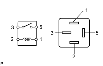
INSPECT F/PMP RELAY
-
Remove the F/PMP relay from the No. 2 relay block.
-
Measure the resistance according to the value(s) in the table below.
Standard Resistance Tester Connection Condition Specified Condition 3 - 4 No battery voltage is applied across terminals 1 and 2 Below 1 Ω 3 - 4 Battery voltage is applied across terminals 1 and 2 10 kΩ or higher If the result is not as specified, replace the relay.
-
-
INSTALL NO. 2 RELAY BLOCK COVER
-
CONNECT CABLE TO NEGATIVE BATTERY TERMINAL
Note
When disconnecting the cable, some systems need to be initialized after the cable is reconnected Click here.
-
INSTALL ENGINE ROOM SIDE COVER LH (for LHD)
-
Install the engine room side cover LH with the 5 clips.
-
-
INSTALL ENGINE ROOM SIDE COVER LH (for RHD)
-
Install the engine room side cover LH with the 4 clips.
-
-
INSTALL COOL AIR INTAKE DUCT SEAL
-
Install the cool air intake duct seal with the 9 clips.
-