AIR FUEL RATIO SENSOR ON-VEHICLE INSPECTION

-
INSPECT AIR FUEL RATIO SENSOR (for Bank 1)
-
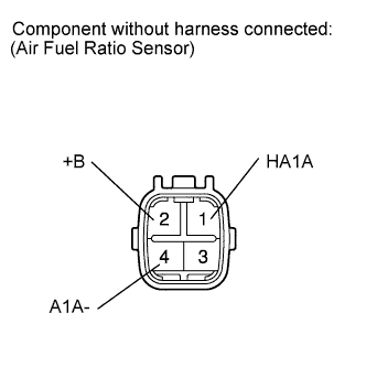
Disconnect the air fuel ratio sensor connector.
-
Measure the resistance according to the value(s) in the table below.
Standard Resistance Tester Connection Condition Specified Condition 1 (HA1A) - 2 (+B) 20°C (68°F) 1.8 to 3.4 Ω 1 (HA1A) - 4 (A1A-) Always 10 kΩ or higher If the result is not as specified, replace the air fuel ratio sensor.
-
-
INSPECT AIR FUEL RATIO SENSOR (for Bank 2)
-
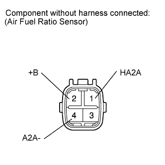
Disconnect the air fuel ratio sensor connector.
-
Measure the resistance according to the value(s) in the table below.
Standard Resistance Tester Connection Condition Specified Condition 1 (HA2A) - 2 (+B) 20°C (68°F) 1.8 to 3.4 Ω 1 (HA2A) - 4 (A2A-) Always 10 kΩ or higher If the result is not as specified, replace the air fuel ratio sensor.
-
-
INSPECT AIR-FUEL RATIO COMPENSATION SYSTEM
Tech Tips
Malfunctioning areas can be identified by performing the Control the Injection Volume for A/F sensor function provided in the Active Test. The Control the Injection Volume for A/F sensor function can help to determine whether the air fuel ratio sensor, heated oxygen sensor and other potential trouble areas are malfunctioning.
The following instructions describe how to conduct the Control the Injection Volume for A/F sensor operation using the intelligent tester.
-
Connect the intelligent tester to the DLC3.
-
Start the engine and turn the intelligent tester ON.
-
Warm up the engine at an engine speed of 2500 rpm for approximately 90 seconds.
-
Enter the following menus: Powertrain / Engine / Active Test / Control the Injection Volume for A/F sensor.
-
Perform the Active Test operation with the engine in an idling condition (press the RIGHT or LEFT button to change the fuel injection volume).
-
Monitor the output voltages of the air-fuel ratio and heated oxygen sensors (AFS B1 S1 and O2S B1 S2 or AFS B2 S1 and O2S B2 S2) displayed on the intelligent tester.
Tech Tips
-
The Control the Injection Volume for A/F operation lowers the fuel injection volume by 12.5% or increases the injection volume by 25%.
-
Each sensor reacts in accordance with increases and decreases in the fuel injection volume.
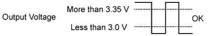
Tester Display (Sensor) Injection Volume Status Voltage AFS B1 S1 or AFS B2 S1
(air fuel ratio)
+25% Rich Less than 3.0 V AFS B1 S1 or AFS B2 S1
(air fuel ratio)
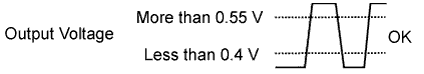
-12.5% Lean More than 3.35 V O2S B1 S2 or O2S B2 S2
(heated oxygen)
+25% Rich More than 0.55 V O2S B1 S2 or O2S B2 S2
(heated oxygen)
-12.5% Lean Less than 0.4 V Note
The air fuel ratio sensor has an output delay of a few seconds and the heated oxygen sensor has a maximum output delay of approximately 20 seconds.
Case A/F Sensor (Sensor 1) Output Voltage HO2 Sensor (Sensor 2) Output Voltage Main Suspected Trouble Area 1 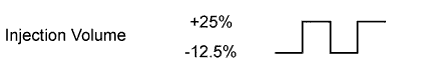
- 2 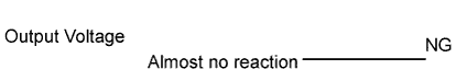
-
Air fuel ratio sensor
-
Air fuel ratio sensor heater
-
Air fuel ratio sensor circuit
3
-
Heated oxygen sensor
-
Heated oxygen sensor heater
-
Heated oxygen sensor circuit
4
-
Injector
-
Fuel pressure
-
Gas leaks from exhaust system (Air fuel ratio extremely rich or lean)
-
Following the Control the Injection Volume for A/F sensor procedure enables technicians to check and graph the voltage outputs of both the air fuel ratio and heated oxygen sensors.
-
To display the graph, enter the following menus: Powertrain / Engine / Active Test / Control the Injection Volume for A/F Sensor / A/F Control System / AFS B1 S1 and O2S B1 S2 or AFS B2 S1 and O2S B2 S2.
-