IGNITION COIL AND SPARK PLUG INSTALLATION

-
INSTALL SPARK PLUG
-
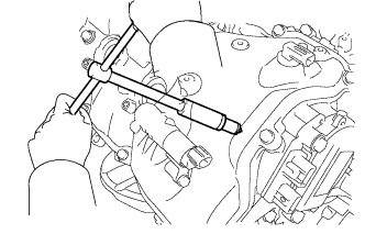
Using a 16 mm plug wrench, install the 8 spark plugs.
- Torque:
- 21 N*m { 214 kgf*cm, 15 ft.*lbf }
-
-
INSTALL IGNITION COIL ASSEMBLY
-
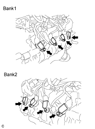
Install the 8 ignition coil assemblies with the 8 bolts.
Note
Do not damage the ignition coil assemblies when installing them.
- Torque:
- 9.0 N*m { 92 kgf*cm, 80 in.*lbf }
-
Connect the 8 ignition coil connectors.
-
-
INSTALL WIRE HARNESS CLAMP BRACKET (for LHD)
-
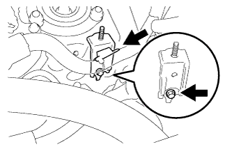
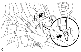
Install the wire harness clamp bracket with the bolt.
- Torque:
- 8.0 N*m { 82 kgf*cm, 71 in.*lbf }
-
Install the wire harness clamp to the clamp bracket.
-
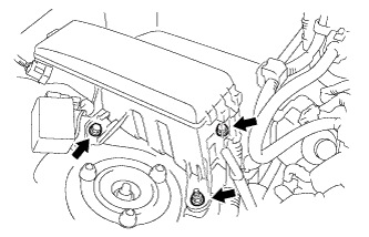
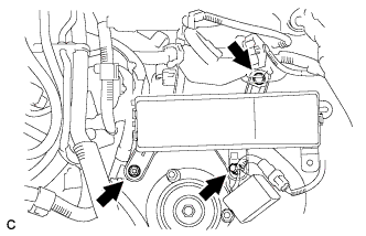
Install the No. 7 engine room relay block with the 2 bolts and nut.
- Torque:
- 8.0 N*m { 82 kgf*cm, 71 in.*lbf }
-
-
INSTALL WIRE HARNESS CLAMP BRACKET (for RHD)
-
Install the wire harness clamp bracket with the bolt.
- Torque:
- 8.0 N*m { 82 kgf*cm, 71 in.*lbf }
-
Install the wire harness clamp to the clamp bracket.
-
Install the No. 7 engine room relay block with the 2 bolts and nut.
- Torque:
- 8.0 N*m { 82 kgf*cm, 71 in.*lbf }
-
-
INSTALL BATTERY TRAY (for LHD)
-
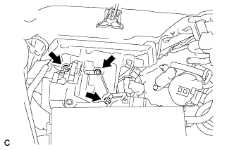
Install the battery tray with the 3 bolts.
- Torque:
- 5.4 N*m { 55 kgf*cm, 48 in.*lbf }
-
-
INSTALL BATTERY TRAY (for RHD)
-
Install the battery tray with the 3 bolts.
- Torque:
- 5.4 N*m { 55 kgf*cm, 48 in.*lbf }
-
-
INSTALL POWER STEERING ECU ASSEMBLY
-
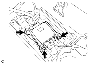
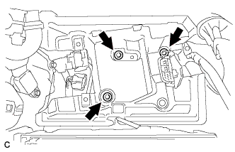
Install the power steering ECU assembly to the battery tray with the 3 bolts.
- Torque:
- 7.5 N*m { 76 kgf*cm, 66 in.*lbf }
-
Connect the connectors (A), (B) and (C) to the power steering ECU assembly.
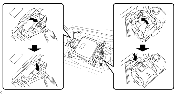
-
Securely lock the connectors (A) and (B).
-
-
INSTALL NO. 1 BATTERY TRAY SUPPORT
-
INSTALL BATTERY (for LHD)
-
Install the battery.
-
Install the battery insulator.
-
Install the battery clamp with a nut.
- Torque:
- 2.9 N*m { 30 kgf*cm, 26 in.*lbf }
-
Connect the cable to the positive (+) battery terminal.
- Torque:
- 5.4 N*m { 55 kgf*cm, 48 in.*lbf }
-
Connect the 2 clamps.
-
-
INSTALL BATTERY (for RHD)
-
Install the battery.
-
Install the battery insulator.
-
Install the battery clamp with a nut.
- Torque:
- 2.9 N*m { 30 kgf*cm, 26 in.*lbf }
-
Connect the cable to the positive (+) battery terminal.
- Torque:
- 5.4 N*m { 55 kgf*cm, 48 in.*lbf }
-
Connect the 2 clamps.
-
-
INSTALL AIR CLEANER CAP SUB-ASSEMBLY
-
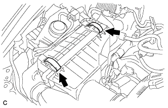
Install the air cleaner cap sub-assembly with air cleaner hose and lock the 2 clamps.
Tech Tips
Tightening torque for the hose clamp located between the air cleaner cap sub-assembly and air cleaner hose assembly is as follows.
- Torque:
- 4.0 N*m { 41 kgf*cm, 35 in.*lbf }
-
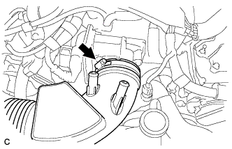
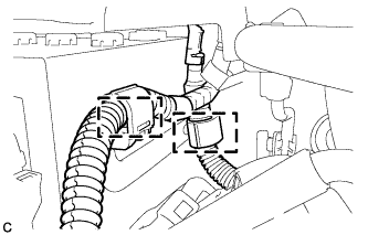
Connect the air cleaner hose to the throttle body with the hose clamp.
- Torque:
- 4.0 N*m { 41 kgf*cm, 35 in.*lbf }
-
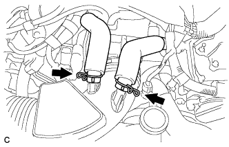
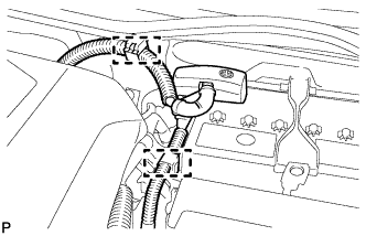
Connect the 2 ventilation hoses with the 2 hose clamps.
-
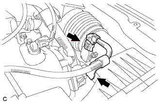
Connect the mass air flow meter connector and wire harness clamp.
-
-
INSTALL ENGINE ROOM SIDE COVER LH (for LHD)
-

Install the engine room side cover LH with the 5 clips.
-
-
INSTALL ENGINE ROOM SIDE COVER LH (for RHD)
-
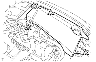
Install the engine room side cover LH with the 4 clips.
-
-
INSTALL ENGINE ROOM SIDE COVER RH (for LHD)
-
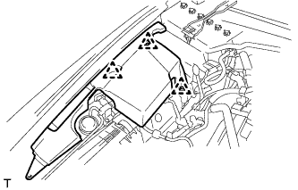
Install the engine room side cover RH with the 3 clips.
-
-
INSTALL ENGINE ROOM SIDE COVER RH (for RHD)
-
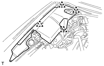
Install the engine room side cover RH with the 4 clips.
-
-
INSTALL COOL AIR INTAKE DUCT SEAL
-
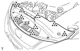
Install the cool air intake duct seal with the 9 clips.
-
-
INSTALL V-BANK COVER SUB-ASSEMBLY
-
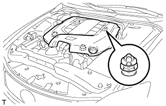
Engage the 4 clips to install the V-bank cover sub-assembly.
Note
-
Be sure to engage the clips securely.
-
Do not apply excessive force or hit the cover to engage the clips. This may cause the cover to break.
-
-
-
CONNECT CABLE TO NEGATIVE BATTERY TERMINAL
Note
When disconnecting the cable, some systems need to be initialized after the cable is reconnected Click here.