CAMSHAFT POSITION SENSOR ON-VEHICLE INSPECTION

-
CHECK CAMSHAFT POSITION SENSOR OUTPUT VOLTAGE
-
Remove the V-bank cover sub-assembly Click here.
-
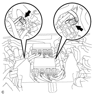
Disconnect the 2 fuel delivery pipe connectors.
-
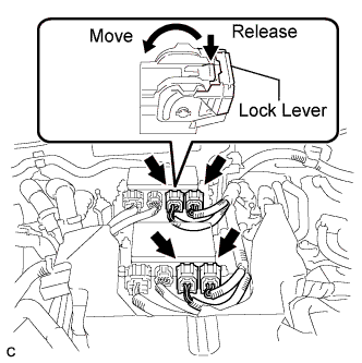
Disconnect the 4 connectors with wire harness locks from the 2 injector drivers.
Tech Tips
-
To release each connector lock, push the claw downward ("Release" in the illustration) and move the lock lever ("Move" in the illustration).
-
Perform this step to prevent the engine from starting.
-
-
Remove the engine room ECU cover Click here.
-
Turn the engine switch on (IG).
Tech Tips
Do not start the engine.
-
Measure the voltage according to the value(s) in the table below.
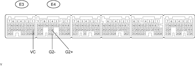
Standard Voltage Tester Connection Switch Condition Specified Condition E3-18 (VC) - E4-32 (G2-) Engine switch on (IG) 5 V -
While turning the crankshaft pulley by hand, measure the voltage between each terminal. Check that the voltage changes between the Hi range and Lo range shown in the table below.
Standard Voltage Tester Connection Switch Condition Specified Condition E4-24 (G2+) - E4-32 (G2-) Engine switch on (IG) 3.75 to 4.50 V (Voltage (Hi))
0.50 to 1.25 V (Voltage (Lo))
-
-
CHECK VVT SENSOR OUTPUT VOLTAGE
-
Remove the V-bank cover sub-assembly Click here.
-
Disconnect the 2 fuel delivery pipe connectors.
-
Disconnect the 4 connectors with wire harness locks from the 2 injector drivers.
Tech Tips
-
To release each connector lock, push the claw downward ("Release" in the illustration) and move the lock lever ("Move" in the illustration).
-
Perform this step to prevent the engine from starting.
-
-
Remove the engine room ECU cover Click here.
-
Turn the engine switch on (IG).
Tech Tips
Do not start the engine.
-
Measure the voltage according to the value(s) in the table below.
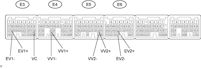
Standard Voltage Tester Connection Switch Condition Specified Condition E3-18 (VC) - E4-33 (VV1-) Engine switch on (IG) 5 V E3-18 (VC) - E5-29 (VV2-) Engine switch on (IG) 5 V E3-18 (VC) - E3-33 (EV1-) Engine switch on (IG) 5 V E3-18 (VC) - E6-29 (EV2-) Engine switch on (IG) 5 V -
While turning the crankshaft pulley by hand, measure the voltage between each terminal. Check that the voltage changes between the Hi range and Lo range shown in the table below.
Standard Voltage Sensor Position Tester Connection Switch Condition Specified Condition Bank 1 (Intake side) E4-25 (VV1+) - E4-33 (VV1-) Engine switch on (IG) 3.75 to 4.50 V (Voltage (Hi))
0.50 to 1.25 V (Voltage (Lo))
Bank 2 (Intake side) E5-19 (VV2+) - E5-29 (VV2-) Engine switch on (IG) 3.75 to 4.50 V (Voltage (Hi))
0.50 to 1.25 V (Voltage (Lo))
Bank 1 (Exhaust side) E3-26 (EV1+) - E3-33 (EV1-) Engine switch on (IG) 3.75 to 4.50 V (Voltage (Hi))
0.50 to 1.25 V (Voltage (Lo))
Bank 2 (Exhaust side) E6-22 (EV2+) - E6-29 (EV2-) Engine switch on (IG) 3.75 to 4.50 V (Voltage (Hi))
0.50 to 1.25 V (Voltage (Lo))
-