CAMSHAFT TIMING CONTROL MOTOR INSTALLATION

-
INSTALL CAMSHAFT TIMING CONTROL WITH EDU MOTOR LH ASSEMBLY
-
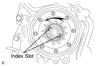
Turn the camshaft timing gear assembly intermediate shaft index slot in the counterclockwise direction by hand, to set it to the maximum retard angle position.
Tech Tips
-
When a camshaft lobe opens a valve, the intermediate shaft becomes difficult to turn.
-
The position where the intermediate shaft stops is the maximum retard angle.
-
-
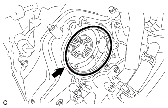
Install a new O-ring to the timing chain cover.
-
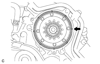
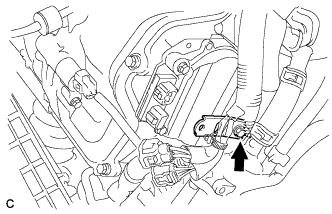
Align the joint of the camshaft timing control with EDU motor LH assembly and the keyway of the camshaft timing gear assembly, and install the camshaft timing control with EDU motor assembly LH with the 3 bolts.
- Torque:
- 21 N*m { 214 kgf*cm, 15 ft.*lbf }
Note
-
Check that [L] is printed on the label of the camshaft timing control with EDU motor LH assembly .
-
Do not allow foreign matter to contact the oil seal face of the camshaft timing control with EDU motor LH assembly (the surface that contacts the timing chain cover sub-assembly).
-
When installing the camshaft timing control with EDU motor LH assembly , do not use excessive force.
-
Align the timing chain cover sub-assembly knock pin with the camshaft timing control with EDU motor LH assembly pin hole to install the camshaft timing control with EDU motor LH assembly .
-
Install the camshaft timing control with EDU motor LH assembly with the arrow facing upward, as shown in the illustration.
-
Do not drop the camshaft timing control with EDU motor LH assembly . If dropped, replace it.
-
Do not disassemble the camshaft timing control with EDU motor LH assembly assembly. If disassembled, replace it.
-
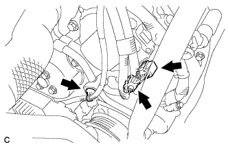
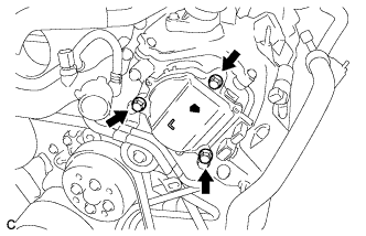
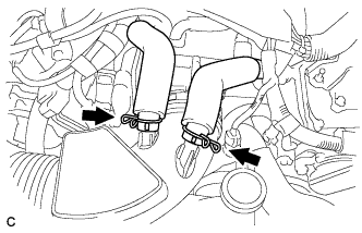
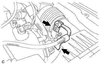
Connect the 2 connectors to the camshaft timing control with EDU motor LH assembly and engine wire clamp.
-
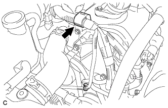
Connect the engine wire clamp.
-
-
INSTALL CAMSHAFT TIMING CONTROL WITH EDU MOTOR RH ASSEMBLY
-
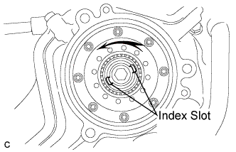
Turn the camshaft timing gear assembly intermediate shaft index slot in the counterclockwise direction by hand, to set it to the maximum retard angle position.
Tech Tips
-
When a camshaft lobe opens a valve, the intermediate shaft becomes difficult to turn.
-
The position where the intermediate shaft stops is the maximum retard angle.
-
-
Install a new O-ring to the timing chain cover.
-
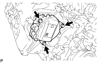
Align the joint of the camshaft timing control with EDU motor RH assembly and the keyway of the camshaft timing gear assembly, and install the camshaft timing control with EDU motor RH assembly with the 3 bolts.
- Torque:
- 21 N*m { 214 kgf*cm, 15 ft.*lbf }
Note
-
Check that [R] is printed on the label of the camshaft timing control with EDU motor RH assembly.
-
Do not allow foreign matter to contact the oil seal face of the camshaft timing control with EDU motor RH assembly (the surface that contacts the timing chain cover sub-assembly).
-
When installing the camshaft timing control with EDU motor RH assembly, do not use excessive force.
-
Align the timing chain cover sub-assembly knock pin with the camshaft timing control with EDU motor RH assembly pin hole to install the camshaft timing control with EDU motor RH assembly.
-
Install the camshaft timing control with EDU motor RH assembly with the arrow facing upward, as shown in the illustration.
-
Do not drop the camshaft timing control with EDU motor RH assembly. If dropped, replace it.
-
Do not disassemble the camshaft timing control with EDU motor RH assembly assembly. If disassembled, replace it.
-
Install the engine wire bracket with the bolt.
- Torque:
- 10 N*m { 102 kgf*cm, 7 ft.*lbf }
-
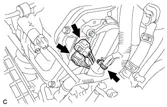
Connect the 2 connectors to the camshaft timing control with EDU motor RH assembly and engine wire clamp.
-
-
INSTALL AIR CLEANER CAP SUB-ASSEMBLY
-
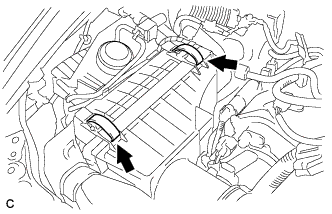
Install the air cleaner cap sub-assembly with air cleaner hose and lock the 2 clamps.
Tech Tips
Tightening torque for the hose clamp located between the air cleaner cap sub-assembly and air cleaner hose assembly is as follows.
- Torque:
- 4.0 N*m { 41 kgf*cm, 35 in.*lbf }
-
Connect the air cleaner hose to the throttle body with the hose clamp.
- Torque:
- 4.0 N*m { 41 kgf*cm, 35 in.*lbf }
-
Connect the 2 ventilation hoses with the 2 hose clamps.
-
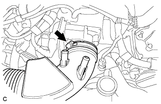
Connect the mass air flow meter connector and wire harness clamp.
-
-
CONNECT CABLE TO NEGATIVE BATTERY TERMINAL
Note
When disconnecting the cable, some systems need to be initialized after the cable is reconnected Click here.
-
INSTALL V-BANK COVER SUB-ASSEMBLY
-
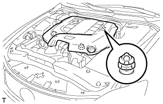
Engage the 4 clips to install the V-bank cover sub-assembly.
Note
-
Be sure to engage the clips securely.
-
Do not apply excessive force or hit the cover to engage the clips. This may cause the cover to break.
-
-