CAMSHAFT OIL CONTROL VALVE INSTALLATION

-
INSTALL CAMSHAFT TIMING OIL CONTROL VALVE ASSEMBLY LH
-
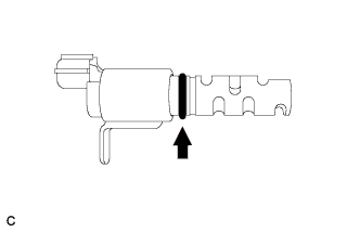
Apply a light coat of engine oil to a new O-ring, and install it to the camshaft timing oil control valve assembly LH.
-
Install the camshaft timing oil control valve assembly LH with the bolt.
- Torque:
- 10 N*m { 102 kgf*cm, 7 ft.*lbf }
Note
-
Do not allow foreign matter to contact the oil seal face of the camshaft timing oil control valve assembly LH (the surface that contacts the cylinder head cover sub-assembly).
-
Be careful that the O-ring is not cracked or does not jump out of position when installing the camshaft timing oil control valve assembly LH.
-
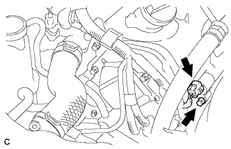
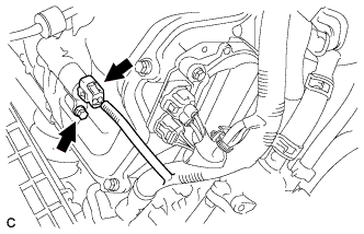
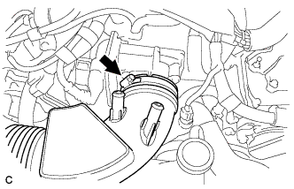
Connect the camshaft timing oil control valve connector.
-
-
INSTALL CAMSHAFT TIMING OIL CONTROL VALVE ASSEMBLY RH
-
Apply a light coat of engine oil to a new O-ring, and install it to the camshaft timing oil control valve RH.
-
Install the camshaft timing oil control valve assembly RH with the bolt.
- Torque:
- 10 N*m { 102 kgf*cm, 7 ft.*lbf }
Note
-
Do not allow foreign matter to contact the oil seal face of the camshaft timing oil control valve assembly RH (the surface that contacts the cylinder head cover sub-assembly).
-
Be careful that the O-ring is not cracked or does not jump out of position when installing the camshaft timing oil control valve assembly RH.
-
Connect the camshaft timing oil control valve connector.
-
-
INSTALL AIR CLEANER CAP SUB-ASSEMBLY
-
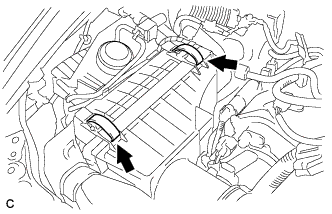
Install the air cleaner cap sub-assembly with air cleaner hose and lock the 2 clamps.
Tech Tips
Tightening torque for the hose clamp located between the air cleaner cap sub-assembly and air cleaner hose assembly is as follows.
- Torque:
- 4.0 N*m { 41 kgf*cm, 35 in.*lbf }
-
Connect the air cleaner hose to the throttle body with the hose clamp.
- Torque:
- 4.0 N*m { 41 kgf*cm, 35 in.*lbf }
-
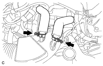
Connect the 2 ventilation hoses with the 2 hose clamps.
-
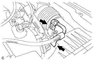
Connect the mass air flow meter connector and wire harness clamp.
-
-
INSPECT FOR OIL LEAK
-
INSTALL V-BANK COVER SUB-ASSEMBLY
-
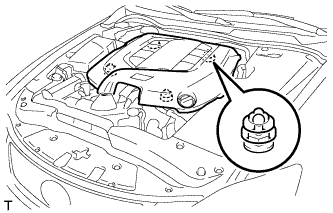
Engage the 4 clips to install the V-bank cover sub-assembly.
Note
-
Be sure to engage the clips securely.
-
Do not apply excessive force or hit the cover to engage the clips. This may cause the cover to break.
-
-