SFI SYSTEM MIL Circuit
DESCRIPTION
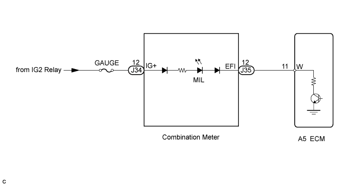
The MIL (Malfunction Indicator Lamp) is used to indicate vehicle malfunction detections by the ECM. By turning the engine switch on (IG), power is supplied to the MIL circuit, and the ECM provides the circuit ground which illuminates the MIL.
The MIL operation can be checked visually:
When the engine switch is first turned on (IG), the MIL should be illuminated and should then turn off. If the MIL remains illuminated or is not illuminated, conduct the following troubleshooting procedure.
If the ECM detects trouble, the MIL illuminates. At this time, the ECM records a DTC in the memory.
WIRING DIAGRAM
INSPECTION PROCEDURE
PROCEDURE
-
CHECK THAT MIL IS ILLUMINATED
-
Turn the engine switch on (IG).
-
Check the illumination of the MIL.
Result Result Proceed to MIL remains illuminated (Even after engine switch on (IG) and several seconds have passed, MIL still remains illuminated) A MIL remains off (Does not illuminate at all) B MIL illuminates for several seconds, but turns off after engine is started C
B 
CHECK THAT ENGINE STARTS Click here
C 
SYSTEM OK
A 
-
-
CHECK IF MIL TURNS OFF
-
Connect the intelligent tester to the DLC3.
-
Turn the engine switch on (IG) and turn the tester ON.
-
Check if DTCs have been stored Click here. If DTCs are present, write them down.
-
Clear the DTCs Click here.
-
Check that the MIL turns off.
OK MIL turns off.
NG
CHECK HARNESS AND CONNECTOR (FOR SHORT) Click here
OK 
REPAIR CIRCUITS INDICATED BY OUTPUT DTC
-
-
CHECK HARNESS AND CONNECTOR (FOR SHORT)
-
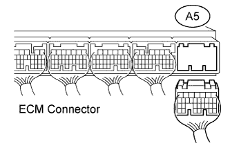
Disconnect the ECM connector.
-
Turn the engine switch on (IG).
-
Check that the MIL is not illuminated.
OK MIL is not illuminated. -
Reconnect the ECM connector.
NG
CHECK HARNESS AND CONNECTOR (COMBINATION METER - ECM) Click here
OK
REPLACE ECM Click here
-
-
CHECK HARNESS AND CONNECTOR (COMBINATION METER - ECM)
-
Disconnect the combination meter connector.
-
Disconnect the ECM connector.
-
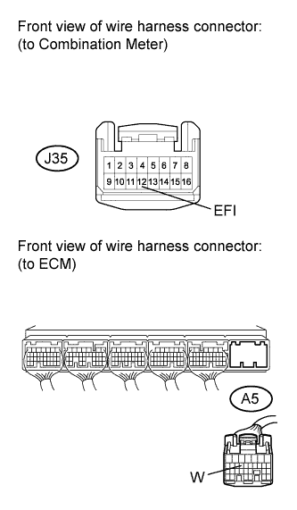
Measure the resistance according to the value(s) in the table below.
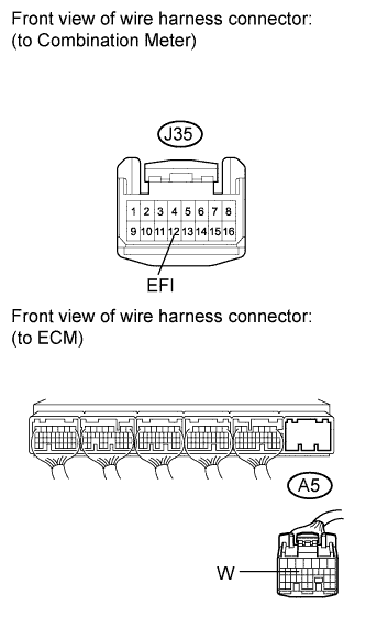
Standard Resistance (Check for Short) Tester Connection Condition Specified Condition J35-12 (EFI) or A5-11 (W) - Body ground Always 10 kΩ or higher -
Reconnect the ECM connector.
-
Reconnect the combination meter connector.
NG
REPAIR OR REPLACE HARNESS OR CONNECTOR
OK
REPAIR OR REPLACE COMBINATION METER ASSEMBLY Click here
-
-
CHECK THAT ENGINE STARTS
-
Start the engine.
Result Result Proceed to Engine starts A Engine does not start* B Tech Tips
*: The tester cannot communicate with the ECM.
B
GO TO VC OUTPUT CIRCUIT Click here
A
-
-
CHECK HARNESS AND CONNECTOR (ECM TERMINAL VOLTAGE)
-
Disconnect the ECM connector.
-
Turn the engine switch on (IG).
-
Measure the voltage according to the value(s) in the table below.
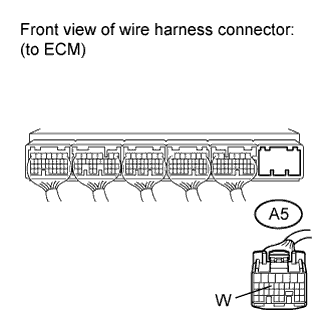
Standard Voltage Tester Connection Switch Condition Specified Condition A5-11 (W) - Body ground Engine switch on (IG) 11 to 14 V -
Reconnect the ECM connector.
NG
CHECK HARNESS AND CONNECTOR (COMBINATION METER - ECM) Click here
OK
REPLACE ECM Click here
-
-
CHECK HARNESS AND CONNECTOR (COMBINATION METER - ECM)
-
Disconnect the combination meter connector.
-
Disconnect the ECM connector.
-
Measure the resistance according to the value(s) in the table below.
Standard Resistance (Check for Open) Tester Connection Condition Specified Condition J35-12 (EFI) - A5-11 (W) Always Below 1 Ω -
Reconnect the combination meter connector and ECM connector.
NG
REPAIR OR REPLACE HARNESS OR CONNECTOR
OK
REPLACE COMBINATION METER ASSEMBLY Click here
-