SFI SYSTEM Fuel Pump Control Circuit
DESCRIPTION
Refer to DTC P0230 Click here.
WIRING DIAGRAM
Refer to DTC P0230 Click here.
INSPECTION PROCEDURE
PROCEDURE
-
CHECK FUEL PUMP OPERATION
-
Check the fuel pump operation Click here.
NG 
PERFORM ACTIVE TEST USING INTELLIGENT TESTER (OPERATE CIRCUIT OPENING RELAY) Click here
OK 
-
-
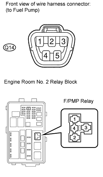
INSPECT F/PMP RELAY
-
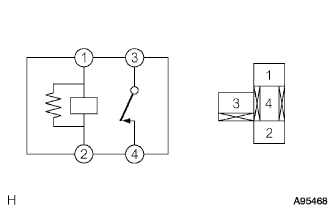
Remove the F/PMP relay from the engine room No. 2 relay block.
-
Measure the resistance according to the value(s) in the table below.
Standard Resistance Tester Connection Condition Specified Condition 3 - 4 When no battery voltage applied to terminals 1 and 2 Below 1 Ω 3 - 4 When battery voltage applied to terminals 1 and 2 10 kΩ or higher -
Reinstall the F/PMP relay.
NG 
REPLACE F/PMP RELAY
OK
-
-
INSPECT FUEL PUMP RESISTOR
-
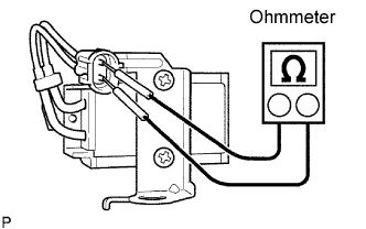
Disconnect the fuel pump resister connector.
-
Measure the resistance according to the value(s) in the table below.
Standard Resistance Tester Connection Condition Specified Condition 1 - 2 20°C (68°F) 0.30 to 0.34 Ω -
Reconnect the fuel pump resister connector.
NG
REPLACE FUEL PUMP RESISTOR Click here
OK
-
-
CHECK HARNESS AND CONNECTOR (F/PMP RELAY - FUEL PUMP RESISTOR)
-
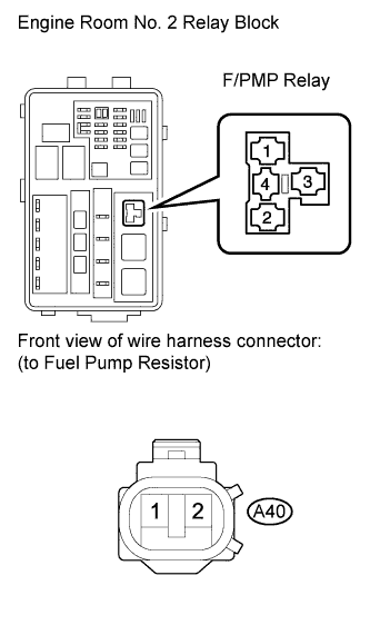
Remove the F/PMP relay from the engine room No. 2 relay block.
-
Disconnect the fuel pump resistor connector.
-
Measure the resistance according to the value(s) in the table below.
Standard Resistance (Check for Open) Tester Connection Condition Specified Condition F/PMP relay (4) - Fuel pump resistor (A40-2) Always Below 1 Ω F/PMP relay (3) - Fuel pump resistor (A40-1) Always Below 1 Ω Standard Resistance (Check for Short) Tester Connection Condition Specified Condition Fuel pump relay (4) or Fuel pump resistor (A40-2) - Body ground Always 10 kΩ or higher Fuel pump relay (3) or Fuel pump resistor (A40-1) - Body ground Always 10 kΩ or higher -
Reinstall the F/PMP relay.
-
Reconnect the fuel pump resister connector.
NG
REPAIR OR REPLACE HARNESS OR CONNECTOR
OK 
PROCEED TO NEXT CIRCUIT INSPECTION SHOWN IN PROBLEM SYMPTOMS TABLE Click here
-
-
PERFORM ACTIVE TEST USING INTELLIGENT TESTER (OPERATE CIRCUIT OPENING RELAY)
-
Connect the intelligent tester to the DLC3.
-
Turn the engine switch on (IG) and turn the tester ON.
-
Enter the following menus: Powertrain / Engine / Active Test /Activate the Fuel Pump Speed Control.
-
Check the operation of the relay while operating it using the tester.
OK Operating noise can be heard from the relay.
NG
INSPECT FUSE (F/PMP FUSE) Click here
OK
-
-
INSPECT FUEL PUMP
-
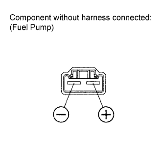
Inspect fuel pump resistance.
-
Remove the fuel pump.
-
Measure the resistance according to the value(s) in the table below.
Standard Resistance Tester Connection Condition Specified Condition 4 - 5 20°C (68°F) 0.2 to 3.0 Ω
-
-
Inspect fuel pump operation.
-
Apply battery voltage to both terminals. Check that the pump operates.
Note
-
These tests must be done quickly (within 10 seconds) to prevent the coil from burning out.
-
Keep the fuel pump as far away from the battery as possible.
-
Always turn the voltage on and off on the battery side, not the fuel pump side.
-
-
Reinstall the fuel pump.
-
NG
REPLACE FUEL PUMP Click here
OK
-
-
CHECK HARNESS AND CONNECTOR (FUEL PUMP - F/PMP RELAY AND BODY GROUND)
-
Disconnect the fuel pump connector.
-
Remove the F/PMP relay from the engine room No. 2 relay block.
-
Check the harness and the connectors between the fuel pump and the F/PMP relay.
-
Measure the resistance according to the value(s) in the table below.
Standard Resistance (Check for Open) Tester Connection Condition Specified Condition Fuel pump (Q14-4) - F/PMP relay (4) Always Below 1 Ω Standard Resistance (Check for Short) Tester Connection Condition Specified Condition Fuel pump (Q14-4) or F/PMP (4) - Body ground Always 10 kΩ or higher
-
-
Check the harness and the connectors between the fuel pump and body ground.
-
Measure the resistance according to the value(s) in the table below.
Standard Resistance (Check for Open) Tester Connection Condition Specified Condition Fuel pump (Q14-5) - Body ground Always 10 kΩ or higher
-
-
Reinstall the F/PMP relay to the engine room No. 2 relay block.
-
Reconnect the fuel pump connector.
NG
REPAIR OR REPLACE HARNESS OR CONNECTOR
OK
-
-
CHECK HARNESS AND CONNECTOR (INTEGRATION RELAY - F/PMP RELAY)
-
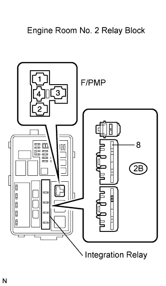
Remove the integration relay from the engine room No. 2 relay block.
-
Remove the F/PMP relay from the engine room No. 2 relay block.
-
Measure the resistance according to the value(s) in the table below.
Standard Resistance (Check for Open) Tester Connection Condition Specified Condition Integration relay (2B-8) - F/PMP relay (1) Always Below 1 Ω Integration relay (2B-8) - F/PMP relay (3) Always Below 1 Ω Standard Resistance (Check for Short) Tester Connection Condition Specified Condition C/OPN relay (2B-8) or F/PMP relay (1) - Body ground Always 10 kΩ or higher C/OPN relay (2B-8) or F/PMP relay (3) - Body ground Always 10 kΩ or higher -
Reinstall the relays.
NG
REPAIR OR REPLACE HARNESS OR CONNECTOR
OK
-
-
CHECK HARNESS AND CONNECTOR (FUEL PUMP - BODY GROUND)
-
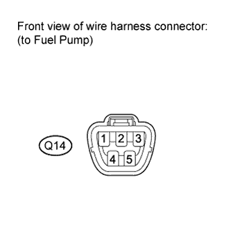
Disconnect the fuel pump connector.
-
Measure the resistance according to the value(s) in the table below.
Standard Resistance (Check for Open) Tester Connection Condition Specified Condition Fuel pump (Q14-5) - Body ground Always Below 1 Ω -
Reconnect the fuel pump connector.
NG
REPAIR OR REPLACE HARNESS OR CONNECTOR
OK
-
-
CHECK FUEL LINE
-
Check the fuel lines for leaks or blockage.
OK No leaks or blockage
NG
REPAIR OR REPLACE FUEL LINE
OK
REPAIR OR REPLACE FUEL SYSTEM (PRESSURE REGULATOR AND FUEL FILTER)
-
-
INSPECT FUSE (F/PMP FUSE)
-
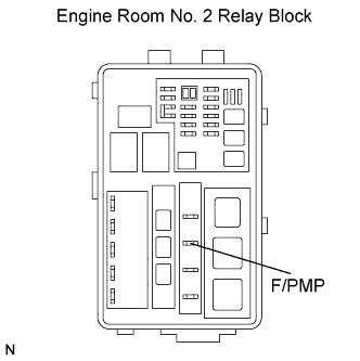
Remove the F/PMP fuse from the engine room No. 2 relay block.
-
Measure the resistance according to the value(s) in the table below.
Standard Resistance Tester Connection Condition Specified Condition F/PMP fuse Always Below 1 Ω -
Reinstall F/PMP the fuse.
NG
CHECK FOR SHORT IN ALL HARNESSES AND CONNECTORS CONNECTED TO FUSE AND REPLACE FUSE (F/PMP FUSE)
OK
-
-
INSPECT INTEGRATION NO.1 RELAY (EFI NO. 2 RELAY)
-
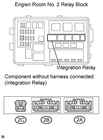
Remove the integration relay from the engine room No. 2 relay block.
-
Measure the resistance according to the value(s) in the table below.
Standard Resistance Tester Connection Condition Specified Condition 2B-4 - 2C-1 When no battery voltage applied to terminals 2B-3 and 2B-2 10 kΩ or higher 2B-4 - 2C-1 When battery voltage applied to terminals 2B-3 and 2B-2 Below 1 Ω -
Reinstall the integration relay.
NG
REPLACE INTEGRATION NO.1 RELAY Click here
OK
-
-
INSPECT INTEGRATION NO.1 RELAY (C/OPN RELAY)
-
Remove the integration relay from the engine room No. 2 relay block.
-
Measure the resistance according to the value(s) in the table below.
Standard Resistance Tester Connection Condition Specified Condition 2B-6 - 2B-8 When no battery voltage applied to terminals 2B-6 and 2B-7 10 kΩ or higher 2B-6 - 2B-8 When battery voltage applied to terminals 2B-6 and 2B-7 Below 1 Ω -
Reinstall the integration relay.
NG
REPLACE INTEGRATION NO.1 RELAY Click here
OK
-
-
INSPECT ECM (FC VOLTAGE)
-
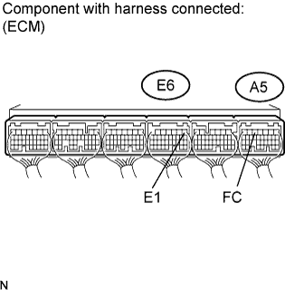
Turn the engine switch on (IG).
-
Measure the voltage according to the value(s) in the table below.
Standard Voltage Tester Connection Switch Condition Specified Condition A5-5 (FC) - E6-1 (E1) Engine Switch on (IG) 11 to 14 V
NG
CHECK AND REPAIR HARNESS AND CONNECTOR (ECM - C/OPN RELAY)
OK
REPLACE ECM Click here
-