SFI SYSTEM, Diagnostic DTC:U0101

| DTC Code | DTC Name |
|---|---|
| U0101 | Lost Communication with TCM |
DESCRIPTION
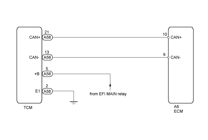
The ECM (engine control unit) intercommunicates with the TCM (transmission control ECU) through the Controller Area Network (CAN).
If there is a problem in this intercommunication, the ECM sets a DTC.
| DTC No. | DTC Detection Condition | Trouble Area |
|---|---|---|
| U0101 |
|
|
WIRING DIAGRAM
INSPECTION PROCEDURE
PROCEDURE
-
CHECK ANY OTHER DTC OUTPUT (IN ADDITION TO DTC U0101)
-
Connect the intelligent tester to the DLC3.
-
Turn the engine switch on (IG).
-
Turn the tester ON.
-
Enter the following menus: Utility / All Codes.
-
Read the DTCs.
Result Result Proceed to DTC U0101 is output A DTC U0101 and other DTCs are output B Tech Tips
If any DTCs other than U0101 are output, troubleshoot those DTCs first.
B 
GO TO DTC CHART
A 
-
-
INSPECT ECU POWER SOURCE CIRCUIT (TCM POWER SOURCE)
-
Disconnect the TCM connector.
-
Turn the engine switch on (IG).
-
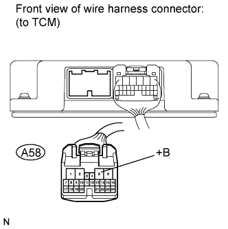
Measure the voltage according to the value(s) in the table below.
Standard Voltage Tester Connection Switch Condition Specified Condition A58-5 (+B) - Body ground Engine switch on (IG) 11 to 14 V -
Reconnect the TCM connector.
NG
GO TO TCM POWER SOURCE CIRCUIT Click here
OK
-
-
CHECK HARNESS AND CONNECTOR (TCM - BODY GROUND)
-
Disconnect the TCM connector.
-
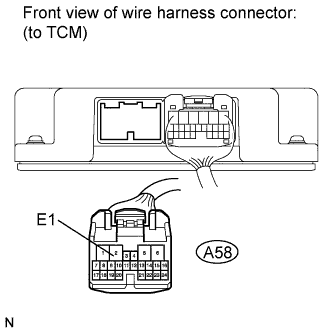
Measure the resistance according to the value(s) in the table below.
Standard Resistance Tester Condition Condition Specified Condition A58-2 (E1) - Body ground Always Below 1 Ω -
Reconnect the TCM connector.
NG
REPAIR OR REPLACE HARNESS OR CONNECTOR (TCM - BODY GROUND)
OK
-
-
CHECK HARNESS AND CONNECTOR (ECM - TCM)
-
Disconnect the ECM connector.
-
Disconnect the TCM connector.
-
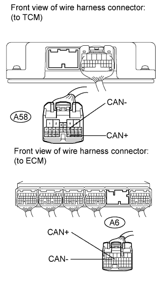
Measure the resistance according to the value(s) in the table below.
Standard Resistance (Check for Open) Tester Connection Condition Specified Condition A6-10 (CAN+) - A58-21 (CAN+) Always Below 1 Ω A6-9 (CAN-) - A58-13 (CAN-) Always Below 1 Ω Standard Resistance (Check for Short) Tester Connection Condition Specified Condition A6-10 (CAN+) or A58-21 (CAN+) - Body ground Always 10 kΩ or higher A6-9 (CAN-) or A58-13 (CAN-) - Body ground Always 10 kΩ or higher -
Reconnect the ECM connector and TCM connector.
NG
REPAIR OR REPLACE HARNESS OR CONNECTOR
OK
-
-
REPLACE ECM
-
Replace the ECM Click here.
NEXT
-
-
CHECK WHETHER DTC OUTPUT RECURS (DTC U0101)
-
Connect the intelligent tester to the DLC3.
-
Turn the engine switch on (IG) and turn the tester ON.
-
Enter the following menus: Powertrain / Engine / DTC.
-
Read the DTC.
Result Result Proceed to DTC is not output A DTC U0101 is output B
B
REPLACE TCM Click here
A 
END
-