SFI SYSTEM, Diagnostic DTC:P2118

| DTC Code | DTC Name |
|---|---|
| P2118 | Throttle Actuator Control Motor Current Range / Performance |
DESCRIPTION
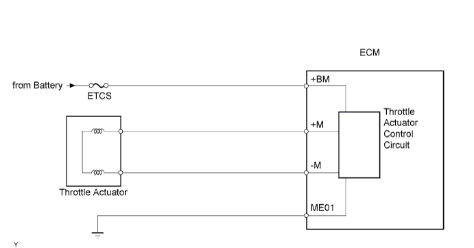
The electronic throttle control system has a dedicated power supply circuit. When the monitored voltage (+BM) is low (less than 4 V), the ECM determines that there is a malfunction in the electronic throttle control system and cuts off the current to the throttle actuator.
When the voltage becomes unstable, the electronic throttle control system itself becomes unstable. For this reason, when the voltage is low, the current to the throttle actuator is cut. If repairs are made and the system returns to normal, turn the engine switch off. The ECM then allows the current to flow to the throttle actuator so that it can be restarted.
Tech Tips
The electronic throttle control system does not use a throttle cable.
| DTC No. | DTC Detection Condition | Trouble Area |
|---|---|---|
| P2118 | Open in electronic throttle control system power source (+BM) circuit (1 trip detection logic) |
|
MONITOR DESCRIPTION
The ECM monitors the battery supply voltage applied to the throttle actuator.
When the power supply voltage (+BM) drops below 4 V for 0.8 seconds or more, the ECM interprets this as an open in the power supply circuit (+BM). The ECM illuminates the MIL and sets the DTC.
If the malfunction is not repaired successfully, the DTC is set 5 seconds after the engine is next started.
FAIL-SAFE
When this DTC, as well as other DTCs relating to electronic throttle control system malfunctions, is set, the ECM enters fail safe mode. During fail safe mode, the ECM cuts the current to the throttle actuator off, and the throttle valve is returned to a 7° throttle angle by the return spring. The ECM then adjusts the engine output by controlling the fuel injection (intermittent fuel cut) and ignition timing, in accordance with the accelerator pedal opening angle, to allow the vehicle to continue running at a minimal speed. If the accelerator pedal is depressed firmly and gently, the vehicle can be driven slowly.
Fail safe mode continues until a pass condition is detected, and the engine switch is then turned off.
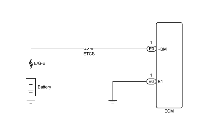
WIRING DIAGRAM
INSPECTION PROCEDURE
Tech Tips
Read freeze frame data using the intelligent tester. Freeze frame data records the engine condition when malfunctions are detected. When troubleshooting, freeze frame data can help determine if the vehicle was moving or stationary, if the engine was warmed up or not, if the air fuel ratio was lean or rich, and other data from the time the malfunction occurred.
PROCEDURE
-
CHECK FUSE (ETCS)
-
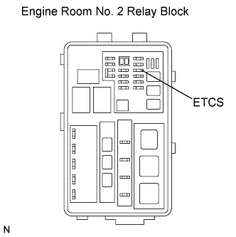
Remove the ETCS fuse from the engine room No. 2 relay block.
-
Measure the resistance according to the value(s) in the table below.
Standard Resistance Tester Connection Condition Specified Condition ETCS fuse Always Below 1 Ω -
Reinstall the ETCS fuse.
NG 
CHECK FOR SHORT IN ALL HARNESSES AND CONNECTORS CONNECTED TO FUSE AND REPLACE FUSE
OK 
-
-
INSPECT ECM (+BM VOLTAGE)
-
Measure the voltage according to the value(s) in the table below.
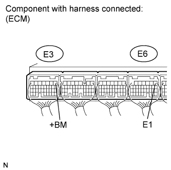
Standard Voltage Tester Connection Condition Specified Condition E3-1 (+BM) - E6-1 (E1) Always 11 to 14 V
NG 
CHECK HARNESS AND CONNECTOR (ECM - BODY GROUND) Click here
OK 
REPLACE ECM Click here
-
-
CHECK HARNESS AND CONNECTOR (ECM - BODY GROUND)
-
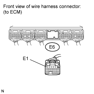
Disconnect the ECM connector.
-
Measure the resistance according to the value(s) in the table below.
Standard Resistance Tester Connection Condition Specified Condition E6-1 (E1) - Body ground Always Below 1 Ω -
Reconnect the ECM connector.
NG
REPAIR OR REPLACE HARNESS OR CONNECTOR
OK
-
-
INSPECT FUSIBLE LINK BLOCK ASSEMBLY (E/G-B FUSE)
-
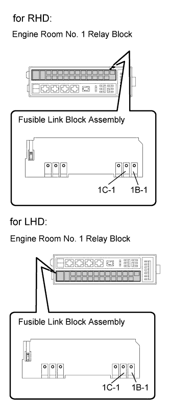
Remove the fusible link from the engine room No. 1 relay block.
-
Measure the resistance according to the value(s) in the table below.
Standard Resistance Tester Connection Condition Specified Condition 1C-1 - 1B-1 Always Below 1 Ω -
Reinstall the fusible link.
NG
REPLACE FUSIBLE LINK BLOCK ASSEMBLY (E/G-B FUSE)
OK
REPAIR OR REPLACE HARNESS OR CONNECTOR (ECM - BATTERY)
-