SFI SYSTEM, Diagnostic DTC:P2102, P2103

| DTC Code | DTC Name |
|---|---|
| P2102 | Throttle Actuator Control Motor Circuit Low |
| P2103 | Throttle Actuator Control Motor Circuit High |
SYSTEM DESCRIPTION
The throttle actuator is operated by the ECM and opens and closes the throttle valve using gears.
The opening angle of the throttle valve is detected by the throttle position sensor, which is mounted on the throttle body. The throttle position sensor provides feedback to the ECM. This feedback allows the ECM to appropriately control the throttle actuator and monitor the throttle opening angle as the ECM responds to driver inputs.
Tech Tips
This electronic throttle control system does not use a throttle cable.
| DTC No. | DTC Detection Condition | Trouble Area |
|---|---|---|
| P2102 | Conditions (a) and (b) continue for 2.0 seconds (1 trip detection logic): (a) Throttle actuator duty ratio 80% or more (b) Throttle actuator current less than 0.5 A |
|
| P2103 | Either of following conditions is met (1 trip detection logic):
|
|
MONITOR DESCRIPTION
The ECM monitors the electrical current through the electronic actuator, and detects malfunctions and open circuits in the throttle actuator based on this value. If the current is outside the standard range, the ECM determines that there is a malfunction in the throttle actuator. In addition, if the throttle valve does not function properly (for example, stuck on), the ECM determines that there is a malfunction. The ECM then illuminates the MIL and sets a DTC.
-
Example:
-
When the electrical current is more than 7 A, or less than 0.5 A and the throttle actuator duty ratio exceeds 80%, the ECM interprets this as the current being outside the standard range, and illuminates the MIL and sets a DTC.
-
If the malfunction is not repaired successfully, a DTC is set when the engine is quickly revved to a high rpm several times after the engine has idled for 5 seconds after engine start.
FAIL-SAFE
When either of these DTCs, as well as other DTCs relating to electronic throttle control system malfunctions, is set, the ECM enters fail safe mode. During fail safe mode, the ECM cuts the current to the throttle actuator off, and the throttle valve is returned to a 7° throttle angle by the return spring. The ECM then adjusts the engine output by controlling the fuel injection (intermittent fuel cut) and ignition timing, in accordance with the accelerator pedal opening angle, to allow the vehicle to continue running at a minimal speed. If the accelerator pedal is depressed firmly and gently, the vehicle can be driven slowly.
Fail-safe mode continues until a pass condition is detected, and the engine switch is then turned off.
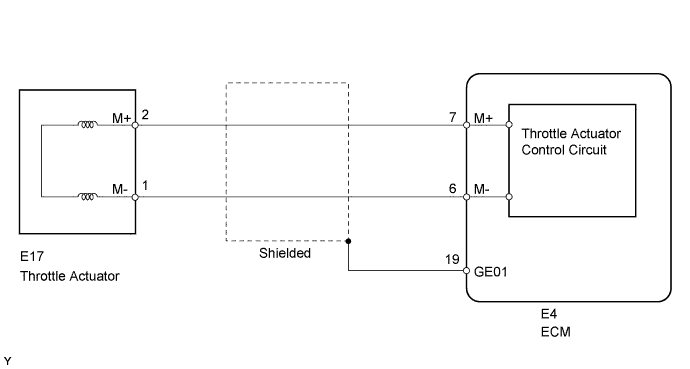
WIRING DIAGRAM
INSPECTION PROCEDURE
Tech Tips
-
Read freeze frame data using the intelligent tester. Freeze frame data records the engine condition when malfunctions are detected. When troubleshooting, freeze frame data can help determine if the vehicle was moving or stationary, if the engine was warmed up or not, if the air fuel ratio was lean or rich, and other data from the time the malfunction occurred.
-
The throttle actuator current (Throttle Motor Current) and the throttle actuator duty ratio (Throttle Motor Open Duty / Throttle Motor Close Duty) can be read using the intelligent tester. However, the ECM shuts off the throttle actuator current when the electronic throttle control system malfunctions.
PROCEDURE
-
INSPECT THROTTLE BODY (RESISTANCE OF THROTTLE ACTUATOR)
-
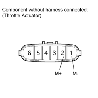
Disconnect the throttle body connector.
-
Measure the resistance according to the value(s) in the table below.
Standard Resistance Tester Connection Condition Specified Condition 2 (M+) - 1 (M-) 20°C (68°F) 0.3 to 100 Ω -
Reconnect the throttle body connector.
NG 
REPLACE THROTTLE BODY Click here
OK 
-
-
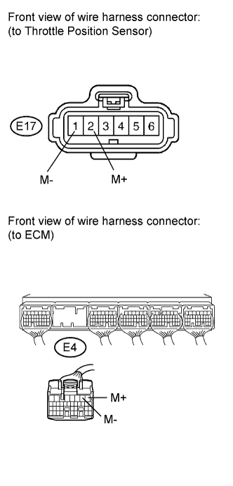
CHECK HARNESS AND CONNECTOR (THROTTLE ACTUATOR - ECM)
-
Disconnect the throttle body connector.
-
Disconnect the ECM connector.
-
Measure the resistance according to the value(s) in the table below.
Standard Resistance (Check for Open) Tester Connection Condition Specified Condition E17-2 (M+) - E4-7 (M+) Always Below 1 Ω E17-1 (M-) - E4-6 (M-) Always Below 1 Ω Standard Resistance (Check for Short) Tester Connection Condition Specified Condition E17-2 (M+) or E4-7 (M+) - Body ground Always 10 kΩ or higher E17-1 (M-) or E4-6 (M-) - Body ground Always 10 kΩ or higher -
Reconnect the throttle body connector and ECM connector.
NG
REPAIR OR REPLACE HARNESS OR CONNECTOR
OK
-
-
REPLACE THROTTLE BODY ASSEMBLY
-
Replace throttle body assembly Click here.
NEXT
-
-
CHECK WHETHER DTC OUTPUT RECURS (THROTTLE ACTIVATOR DTC)
-
Connect the intelligent tester to the DLC3.
-
Turn the engine switch on (IG) and turn the tester ON.
-
Clear the DTC Click here.
-
Start the engine.
-
Drive the vehicle several minutes.
-
Enter the following menus: Powertrain / Engine / DTC.
-
Read the DTC.
Result Result Proceed to DTC P2102 or P2103 is output A DTC is not output B
B
END
A 
REPLACE ECM Click here
-