SFI SYSTEM, Diagnostic DTC:P1362, P1363

| DTC Code | DTC Name |
|---|---|
| P1362 | "B" Camshaft Position Actuator Circuit Open, Low, High Bank1 |
| P1363 | "B" Camshaft Position Actuator Circuit Open, Low, High Bank2 |
DESCRIPTION
Refer to DTC P0010 Click here.
| DTC No. | DTC Detection Condition | Trouble Area |
|---|---|---|
| P1362 | While engine is running, malfunction in rotation direction signal (VTD) of camshaft timing control motor is detected for 3 seconds (1 trip detection logic) |
|
| P1363 | While engine is running, malfunction in rotation direction signal (VTD) of camshaft timing control motor is detected for 3 seconds (1 trip detection logic) |
|
MONITOR DESCRIPTION
This DTC is output when a rotation direction signal malfunction is detected in the intake side camshaft timing control motor. While the engine is running, if a rotation direction signal (VTD) malfunction is detected, a DTC is output (1 trip detection logic).
When there is a malfunction, if the engine is idled for 30 seconds or the vehicle is driven in an urban area for 5 minutes, a DTC is output.
WIRING DIAGRAM
Refer to DTC P1360 Click here.
INSPECTION PROCEDURE
Tech Tips
Read freeze frame data using the intelligent tester. Freeze frame data records the engine condition when malfunctions are detected. When troubleshooting, freeze frame data can help determine if the vehicle was moving or stationary, if the engine was warmed up or not, if the air fuel ratio was lean or rich, and other data from the time the malfunction occurred.
PROCEDURE
-
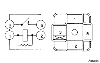
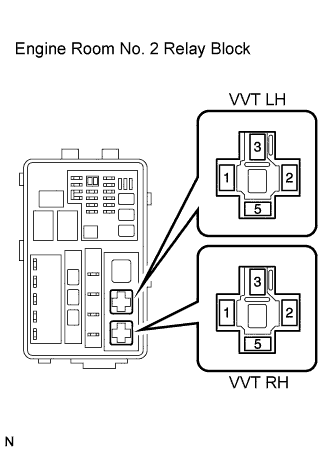
INSPECT VVT RELAY (VVT LH, VVT RH)
-
Remove the VVT LH relay or VVT RH relay from the engine room No. 2 relay block.
-
Measure the resistance according to the value(s) in the table below.
Standard Resistance Tester Connection Condition Specified Condition 3 - 5 When no battery voltage applied to terminals 1 and 2 10 kΩ or higher 3 - 5 When battery voltage applied to terminals 1 and 2 Below 1 Ω -
Reinstall the relay.
NG 
REPLACE VVT RELAY (VVT LH, VVT RH)
OK 
-
-
CHECK HARNESS AND CONNECTOR (CAMSHAFT TIMING CONTROL POWER SOURCE)
-
Disconnect the camshaft timing control motor connector.
-
Turn the engine switch on (IG).
-
Measure the voltage according to the value(s) in the table below.
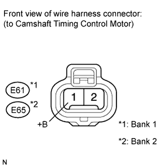
Standard Voltage Tester Connection Condition Specified Condition E61-1 (+B) - Body ground Engine switch on (IG) 11 to 14 V E65-1 (+B) - Body ground -
Reconnect the camshaft timing control motor connector.
NG 
CHECK HARNESS AND CONNECTOR (VVT LH OR VVT RH RELAY POWER SOURCE) Click here
OK
-
-
CHECK HARNESS AND CONNECTOR (CAMSHAFT TIMING CONTROL MOTOR - ENGINE GROUND)
-
Turn the engine switch off.
-
Disconnect the camshaft timing control motor connector.
-
Measure the resistance according to the value(s) in the table below.
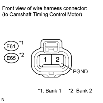
Standard Resistance Tester Connection Condition Specified Condition E61-2 (PGND) - Engine ground Always Below 1 Ω E65-2 (PGND) - Engine ground -
Reconnect the camshaft timing control motor connector.
NG
REPAIR OR REPLACE HARNESS OR CONNECTOR (CAMSHAFT TIMING CONTROL MOTOR - ENGINE GROUND)
OK
-
-
CHECK HARNESS AND CONNECTOR (CAMSHAFT TIMING CONTROL MOTOR - ECM)
-
Disconnect the ECM connector.
-
Disconnect the camshaft timing control motor connector.
-
Measure the resistance according to the value(s) in the table below.
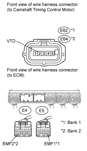
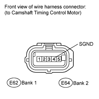
Standard Resistance (Check for Open) Tester Connection Condition Specified Condition E62-2 (VTD) - E5-31 (EMF1) Always Below 1 Ω E64-2 (VTD) - E4-30 (EMF2) Standard Resistance (Check for Short) Tester Connection Condition Specified Condition E62-2 (VTD) or E5-31 (EMF1) - Body ground Always 10 kΩ or higher E64-2 (VTD) or E4-30 (EMF2) - Body ground -
Reconnect the camshaft timing control motor connector and ECM connector.
NG
REPAIR OR REPLACE HARNESS OR CONNECTOR
OK
-
-
CHECK HARNESS AND CONNECTOR (CAMSHAFT TIMING CONTROL MOTOR - ENGINE GROUND)
-
Disconnect the camshaft timing control motor connector.
-
Measure the resistance according to the value(s) in the table below.
Standard Resistance Tester Connection Condition Specified Condition E62-4 (SGND) - Engine ground Always Below 1 Ω E64-4 (SGND) - Engine ground -
Reconnect the camshaft timing control motor connector.
NG
REPAIR OR REPLACE HARNESS OR CONNECTOR (CAMSHAFT TIMING CONTROL MOTOR - ENGINE GROUND)
OK
-
-
REPLACE CAMSHAFT TIMING CONTROL MOTOR (BANK 1 OR BANK 2)
-
Replace the camshaft timing control motor Click here.
NEXT
-
-
CONFIRM WHETHER MALFUNCTION HAS BEEN SUCCESSFULLY REPAIRED
-
Connect the intelligent tester to the DLC3.
-
Start the engine and idled it for 10 seconds.
-
Enter the following menus: Powertrain / Engine / DTC.
-
Read the DTCs.
Result Result Proceed to DTC is not output A Other DTCs output B
B
GO TO DTC CHART Click here
A 
END
-
-
CHECK HARNESS AND CONNECTOR (VVT LH OR VVT RH RELAY POWER SOURCE)
-
Remove the VVT LH or VVT RH relay.
-
Turn the engine switch on (IG).
-
Measure the voltage according to the value(s) in the table below.
Standard Voltage Tester Connection Condition Specified Condition VVT LH relay (1) - Body ground Engine switch on (IG) 11 to 14 V VVT RH relay (1) - Body ground Engine switch on (IG) 11 to 14 V -
Reinstall the relay.
NG
REPAIR OR REPLACE HARNESS OR CONNECTOR (EFI NO. 2 FUSE - VVT LH OR VVT RH RELAY)
OK
-
-
CHECK HARNESS AND CONNECTOR (VVT LH OR VVT RH RELAY - BODY GROUND)
-
Remove the VVT LH or VVT RH relay.
-
Measure the resistance according to the value(s) in the table below.
Standard Resistance Tester Connection Condition Specified Condition VVT LH relay (2) - Body ground Always Below 1 Ω VVT RH relay (2) - Body ground Always Below 1 Ω -
Reinstall the relay.
NG
REPAIR OR REPLACE HARNESS OR CONNECTOR (VVT LH OR VVT RH RELAY - BODY GROUND)
OK
-
-
INSPECT FUSIBLE LINK BLOCK ASSEMBLY (VVT FUSE)
-
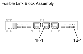
Remove the fusible link block from the engine room No. 1 relay block.
-
Measure the resistance according to the value(s) in the table below.
Standard Resistance Tester Connection Condition Specified Condition 1F-1 - 1B-1 Always Below 1 Ω -
Reinstall the fusible link block assembly.
NG
REPLACE FUSIBLE LINK BLOCK ASSEMBLY (VVT FUSE)
OK
-
-
CHECK HARNESS AND CONNECTOR (VVT LH OR VVT RH RELAY - BATTERY)
-
Remove the VVT LH or VVT RH relay.
-
Turn the engine switch on (IG).
-
Measure the voltage according to the value(s) in the table below.
Standard Voltage Tester Connection Condition Specified Condition VVT LH relay (3) - Body ground Engine switch on (IG) 11 to 14 V VVT RH relay (3) - Body ground Engine switch on (IG) 11 to 14 V -
Reinstall the relay.
NG
REPAIR OR REPLACE HARNESS OR CONNECTOR (VVT LH OR VVT RH RELAY - BATTERY)
OK
REPAIR OR REPLACE HARNESS OR CONNECTOR (VVT LH OR VVT RH RELAY - CAMSHAFT TIMING CONTROL MOTOR)
-