SFI SYSTEM, Diagnostic DTC:P2237, P2238, P2239, P2240, P2241, P2242, P2252, P2253, P2255, P2256

| DTC Code | DTC Name |
|---|---|
| P2237 | Oxygen (A/F) Sensor Pumping Current Circuit / Open (Bank 1 Sensor 1) |
| P2238 | Oxygen (A/F) Sensor Pumping Current Circuit Low (Bank 1 Sensor 1) |
| P2239 | Oxygen (A/F) Sensor Pumping Current Circuit High (Bank 1 Sensor 1) |
| P2240 | Oxygen (A/F) Sensor Pumping Current Circuit / Open (Bank 2 Sensor 1) |
| P2241 | Oxygen (A/F) Sensor Pumping Current Circuit Low (Bank 2 Sensor 1) |
| P2242 | Oxygen (A/F) Sensor Pumping Current Circuit High (Bank 2 Sensor 1) |
| P2252 | Oxygen (A/F) Sensor Reference Ground Circuit Low (Bank 1 Sensor 1) |
| P2253 | Oxygen (A/F) Sensor Reference Ground Circuit High (Bank 1 Sensor 1) |
| P2255 | Oxygen (A/F) Sensor Reference Ground Circuit Low (Bank 2 Sensor 1) |
| P2256 | Oxygen (A/F) Sensor Reference Ground Circuit High (Bank 2 Sensor 1) |
CAUTION / NOTICE / HINT
Tech Tips
-
Although the DTC titles say oxygen sensor, these DTCs relate to the Air-Fuel Ratio (A/F) sensor.
-
Sensor 1 refers to the sensor mounted in front of the Three-Way Catalytic Converter (TWC) and located near the engine assembly.
DESCRIPTION
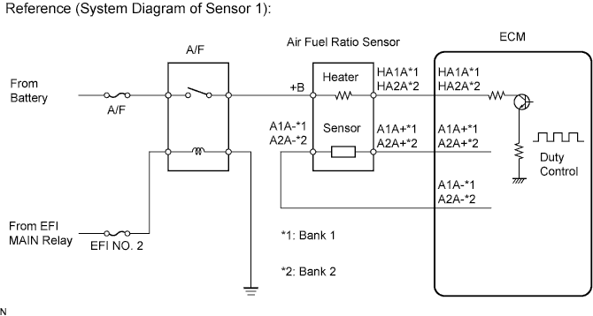
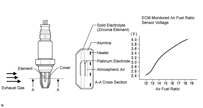
The A/F sensor, which is located between the exhaust manifold and catalyst, consists of alloyed metal elements and a heater.
Depending on the engine operating conditions, the heater heats the sensor elements to activate them. Battery voltage is applied to the heater, the sensor ground is controlled by the ECM using a duty ratio.
The sensor elements convert the oxygen concentration in the exhaust gas into voltage values to output. Based on the voltage, the ECM determines the air-fuel ratio and regulates the fuel injection volume depending on the air-fuel ratio and engine operating conditions. The voltage changes between 0.6 V and 4.5 V while the engine is running. If the air-fuel ratio is lean, which means the oxygen concentration in the exhaust gas is high, the voltage is high. If the air-fuel ratio is rich, which means the oxygen concentration in the exhaust gas is low, the voltage is low.
| DTC No. | DTC Detection Condition | Trouble Area |
|---|---|---|
| P2237 P2240 |
Open in the circuit between terminals A1A+ (A2A+) and A1A- (A2A-) of the air fuel ratio sensor while engine is running (2 trip detection logic) |
|
| P2238 P2241 |
Any of the following conditions are met (2 trip detection logic)
|
|
| P2239 P2242 |
A1A+ (A2A+) voltage more than 4.5 V (2 trip detection logic) |
|
| P2252 P2255 |
A1A- (A2A-) voltage 0.5 V or less (2 trip detection logic) |
|
| P2253 P2256 |
A1A- (A2A-) voltage more than 4.5 V (2 trip detection logic) |
|
MONITOR DESCRIPTION
These DTCs are output when there is an open or short in the air fuel ratio sensor circuit, or if air fuel ratio sensor output drops. To detect these problems, the voltage of the air fuel ratio sensor is monitored when turning the engine switch to the on (IG) position, and the admittance (admittance is an electrical term that indicates the ease of flow of current) is checked while driving. If the voltage of the air fuel ratio sensor is between 0.6 V and 4.5 V, it is considered normal. If the voltage is out of the specified range, or the admittance is less than the standard value, the ECM will determine that there is a malfunction in the air fuel ratio sensor. If the same malfunction is detected in next driving cycle, the MIL will be illuminated and a DTC will be stored.
WIRING DIAGRAM
Refer to DTC P2195 Click here.
INSPECTION PROCEDURE
Tech Tips
Malfunctioning areas can be identified by performing the Control the Injection Volume for A/F Sensor function provided in the Active Test. The Control the Injection Volume for A/F Sensor function can help to determine whether the air fuel ratio sensor, heated oxygen sensor and other potential trouble areas are malfunctioning.
The following instructions describe how to conduct the Control the Injection Volume for A/F Sensor operation using the intelligent tester.
-
Connect the intelligent tester to the DLC3.
-
Start the engine and turn the tester on.
-
Warm up the engine at an engine speed of 2500 rpm for approximately 90 seconds.
-
On the tester, enter the following menus: Powertrain / Engine / Active Test / Control the Injection Volume for A/F Sensor.
-
Perform the Active Test operation with the engine in an idling condition (press the RIGHT or LEFT button to change the fuel injection volume).
-
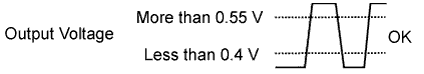
Monitor the output voltages of the air fuel ratio and heated oxygen sensors (AFS Voltage B1S1 and O2S B1S2 or AFS Voltage B2S1 and O2S B2S2) displayed on the tester.
Tech Tips
-
The Control the Injection Volume for A/F Sensor operation lowers the fuel injection volume by 12.5% or increases the injection volume by 25%.
-
Each sensor reacts in accordance with increases and decreases in the fuel injection volume.
| Tester Display (Sensor) | Injection Volume | Status | Voltage |
|---|---|---|---|
| AFS Voltage B1S1 or AFS Voltage B2S1 (Air fuel ratio) |
+25% | Rich | Less than 3.1 V |
| AFS Voltage B1S1 or AFS Voltage B2S1 (Air fuel ratio) |
-12.5% | Lean | More than 3.4 V |
| O2S B1S2 or O2S B2S2 (Heated oxygen) |
+25% | Rich | More than 0.55 V |
| O2S B1S2 or O2S B2S2 (Heated oxygen) |
-12.5% | Lean | Less than 0.4 V |
Note
The air fuel ratio sensor has an output delay of a few seconds and the heated oxygen sensor has a maximum output delay of approximately 20 seconds.
| Case | Air Fuel Ratio Sensor (Sensor 1) Output Voltage | Heated Oxygen Sensor (Sensor 2) Output Voltage | Main Suspected Trouble Area |
|---|---|---|---|
| 1 | 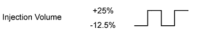 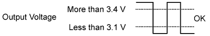 |
 |
- |
| 2 | 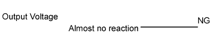 |
|
|
| 3 | |
|
|
| 4 | |
|
|
-
Following the Control the Injection Volume for A/F Sensor procedure enables technicians to check and graph the voltage outputs of both the air fuel ratio and heated oxygen sensors.
-
To display the graph, enter the following menus: Powertrain / Engine / Active Test / Control the Injection Volume for A/F Sensor / All Data / AFS Voltage B1S1 and O2S B1S2 or AFS Voltage B2S1 and O2S B2S2.
Tech Tips
Read freeze frame data using the intelligent tester. Freeze frame data records the engine condition when malfunctions are detected. When troubleshooting, freeze frame data can help determine if the vehicle was moving or stationary, if the engine was warmed up or not, if the air-fuel ratio was lean or rich, and other data from the time the malfunction occurred.
PROCEDURE
-
CHECK HARNESS AND CONNECTOR (AIR FUEL RATIO SENSOR - ECM)
-
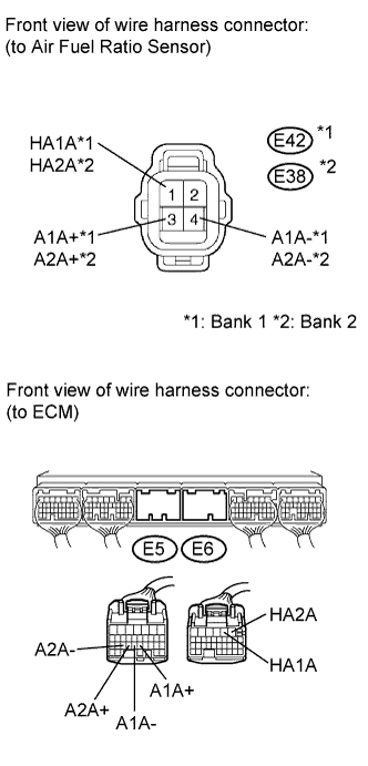
Disconnect the air fuel ratio sensor connectors.
-
Disconnect the ECM connectors.
-
Measure the resistance according to the value(s) in the table below.
Standard resistance (Check for open) Tester Connection Condition Specified Condition E42-1 ( HA1A) - E6-5 (HA1A) Always Below 1 Ω E42-3 (A1A+) - E5-23 (A1A+) Always Below 1 Ω E42-4 (A1A-) - E5-22 (A1A-) Always Below 1 Ω E38-1 (HA2A) - E6-6 (HA2A) Always Below 1 Ω E38-3 (A2A+) - E5-21 (A2A+) Always Below 1 Ω E38-4 (A2A-) - E5-20 (A2A-) Always Below 1 Ω Standard resistance (Check for short) Tester Connection Condition Specified Condition E42-1 ( HA1A) or E6-5 (HA1A) - Body ground Always 10 kΩ or higher E42-3 (A1A+) or E5-23 (A1A+) - Body ground Always 10 kΩ or higher E42-4 (A1A-) or E5-22 (A1A-) - Body ground Always 10 kΩ or higher E38-1 (HA2A) or E6-6 (HA2A) -Body ground Always 10 kΩ or higher E38-3 (A2A+) or E5-21 (A2A+) - Body ground Always 10 kΩ or higher E38-4 (A2A-) or E5-20 (A2A-) - Body ground Always 10 kΩ or higher -
Reconnect the air fuel ratio sensor connectors.
-
Reconnect the ECM connectors.
NG 
REPAIR OR REPLACE HARNESS OR CONNECTOR
OK 
-
-
REPLACE AIR FUEL RATIO SENSOR
-
Replace the air-fuel ratio sensor Click here.
NEXT
-
-
CHECK WHETHER DTC OUTPUT RECURS
-
Connect the intelligent tester to the DLC3.
-
Turn the engine switch on (IG) and turn the tester ON.
-
Clear the DTCs Click here.
-
Start the engine.
-
Allow the engine to idle for 5 minutes or more.
-
Enter the following menus: Powertrain / Engine / DTC / Pending.
-
Read pending DTCs.
Result Display (DTC Output) Proceed to No output A P2237, P2240, P2238, P2241, P2239, P2242, P2252, P2255, P2253 or P2256 B
B
REPLACE ECM Click here
A 
END
-