SFI SYSTEM, Diagnostic DTC:P0724

| DTC Code | DTC Name |
|---|---|
| P0724 | Brake Switch "B" Circuit High |
DESCRIPTION
The purpose of this circuit is to prevent the engine from stalling, while driving in lock-up condition, when brakes are suddenly applied.
When the brake pedal is depressed, this switch sends a signal to the ECM. Then the ECM cancels the operation of the lock-up clutch while braking is in progress.
| DTC No. | DTC Detection Condition | Trouble Area |
|---|---|---|
| P0724 | The stop light switch remains ON even when the vehicle repeats 5 cycles of STOP (less than 3 km/h (1.86 mph)) and GO (30 km/h (18.65 mph) or more) (2 trip detection logic) |
|
MONITOR DESCRIPTION
This DTC indicates that the stop light switch remains ON. When the stop light switch remains ON during "stop and go" driving, the ECM interprets this as a fault in the stop light switch and the MIL comes on and the ECM stores the DTC. The vehicle must stop (less than 1.86 mph [3 km/h]) and go (18.65 mph [30 km/h] or more) 5 times during 2 driving cycles, in order to detect a malfunction.
WIRING DIAGRAM
Refer to DTC P0504 Click here.
INSPECTION PROCEDURE
Tech Tips
Read freeze frame data using the intelligent tester. Freeze frame data records the engine condition when malfunctions are detected. When troubleshooting, freeze frame data can help determine if the vehicle was moving or stationary, if the engine was warmed up or not, if the air fuel ratio was lean or rich, and other data from the time the malfunction occurred.
PROCEDURE
-
READ VALUE USING INTELLIGENT TESTER (STOP LIGHT SWITCH)
-
Connect the intelligent tester to the DLC3.
-
Turn the engine switch on (IG) and turn the tester ON.
-
Enter the following menus: Powertrain / Engine / Data List / All Data / Stop Light Switch.
-
Read the values displayed on the intelligent tester.
OK Item Measurement Item/Range (display) Normal Condition Stop Light Switch Stop light switch status:
ON or OFF
-
ON: Brake pedal is depressed
-
OFF: Brake pedal is released
-
NG 
OK 
CHECK FOR INTERMITTENT PROBLEMS Click here
-
-
INSPECT STOP LIGHT SWITCH ASSEMBLY
-
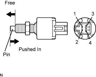
Remove the stop light switch assembly.
-
Measure the resistance according to the value(s) in the table below.
Standard Resistance Tester Connection Switch Condition Specified Condition 1 - 2 Switch pin free Below 1 Ω 3 - 4 10 kΩ or higher 1 - 2 Switch pin pushed in 10 kΩ or higher 3 - 4 Below 1 Ω -
Reinstall the stop light switch assembly.
NG 
REPLACE STOP LIGHT SWITCH ASSEMBLY Click here
OK 
-
-
CHECK HARNESS AND CONNECTOR (STOP LIGHT SWITCH - ECM)
-
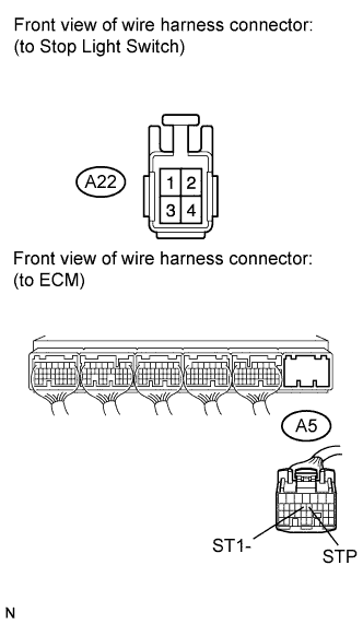
Disconnect the stop light switch connector.
-
Disconnect the ECM connector.
-
Measure the resistance according to the value(s) in the table below.
Standard Resistance (Check for Short) Tester Connection Condition Specified Condition A22-1 or A5-13 (STP) - Body ground Always 10 kΩ or higher A22-3 or A5-12 (ST1-) - Body ground Always -
Reconnect the stop light switch connector and ECM connector.
NG
REPAIR OR REPLACE HARNESS OR CONNECTOR (STOP LIGHT SWITCH - ECM)
OK
REPLACE ECM Click here
-