SFI SYSTEM, Diagnostic DTC:P0504

| DTC Code | DTC Name |
|---|---|
| P0504 | Brake Switch "A" / "B" Correlation |
DESCRIPTION
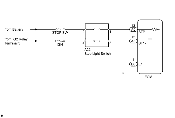
The stop light switch is a duplex system that transmits two signals: STP and ST1-. These two signals are used by the ECM to monitor whether or not the brake system is working properly. If the signals, which indicate the brake pedal is being depressed and released, are detected simultaneously, the ECM interprets this as a malfunction in the stop light switch and sets the DTC.
Tech Tips
The normal conditions are as shown in the table below. The signals can be read using the intelligent tester.
| Signal | Brake Pedal Released | In Transition | Brake Pedal Depressed |
|---|---|---|---|
| STP | OFF | ON | ON |
| ST1- | ON | ON | OFF |
| DTC No. | DTC Detection Condition | Trouble Area |
|---|---|---|
| P0504 | Conditions (a), (b) and (c) continue for 0.5 seconds or more (1 trip detection logic)
|
|
WIRING DIAGRAM
INSPECTION PROCEDURE
Tech Tips
Read freeze frame data using the intelligent tester. Freeze frame data records the engine condition when malfunctions are detected. When troubleshooting, freeze frame data can help determine if the vehicle was moving or stationary, if the engine was warmed up or not, if the air fuel ratio was lean or rich, and other data from the time the malfunction occurred.
PROCEDURE
-
READ VALUE USING INTELLIGENT TESTER (STP SIGNAL AND ST1- VOLTAGE)
-
Connect the intelligent tester to the DLC3.
-
Turn the engine switch on (IG) and turn the tester ON.
-
Enter the following menus: Powertrain / Engine / Data List / All Data / Stop Light Switch.
-
Check the STP signal when the brake pedal is depressed and released.
Standard Brake Pedal Operation Specified Condition Depressed STP signal ON Released STP signal OFF -
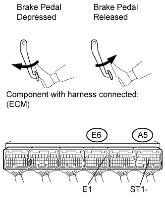
Measure the voltage according to the value(s) in the table below.
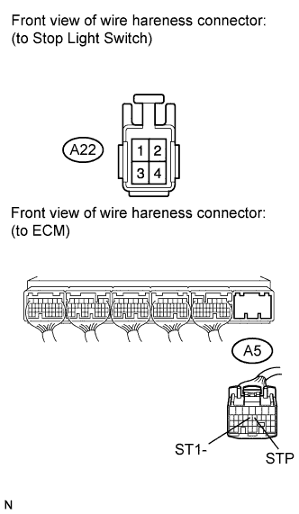
Standard Voltage Tester Connection Condition Specified Condition A5-12 (ST1-) - E6-1 (E1) Brake pedal depressed Below 1.5 V Brake pedal released 7.5 to 14 V
NG 
INSPECT STOP LIGHT SWITCH (POWER SOURCE) Click here
OK 
CHECK FOR INTERMITTENT PROBLEMS Click here
-
-
INSPECT STOP LIGHT SWITCH (POWER SOURCE)
-
Disconnect the stop light switch.
-
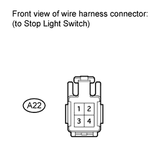
Measure the voltage according to the value(s) in the table below.
Standard Voltage Tester Connection Condition Specified Condition A22-2 - Body ground Always 11 to 14 V A22-3 - Body ground Engine switch on (IG) 11 to 14 V -
Reconnect the stop light switch connector.
NG
INSPECT FUSE (STOP SW AND IGN FUSE) Click here
OK 
-
-
INSPECT STOP LIGHT SWITCH ASSEMBLY
-
Remove the stop light switch assembly.
-
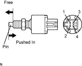
Measure the resistance according to the value(s) in the table below.
Standard Resistance Tester Connection Switch Condition Specified Condition 1 - 2 Switch pin free Below 1 Ω 3 - 4 10 kΩ or higher 1 - 2 Switch pin pushed in 10 kΩ or higher 3 - 4 Below 1 Ω -
Reinstall the stop light switch assembly.
NG 
REPLACE STOP LIGHT SWITCH ASSEMBLY Click here
OK
-
-
CHECK HARNESS AND CONNECTOR (STOP LIGHT SWITCH - ECM)
-
Disconnect the stop light switch connector.
-
Disconnect the ECM connector.
-
Measure the resistance according to the value(s) in the table below.
Standard Resistance (Check for Open) Tester Connection Condition Specified Condition A22-1 - A5-13 (STP) Always Below 1 Ω A22-3 - A5-12 (ST1-) Always Standard Resistance (Check for Short) Tester Connection Condition Specified Condition A22-1 or A5-13 (STP) - Body ground Always 10 kΩ or higher A22-3 or A5-12 (ST1-) - Body ground Always -
Reconnect the stop light switch connector and ECM connector.
NG
REPAIR OR REPLACE HARNESS OR CONNECTOR (STOP LIGHT SWITCH - ECM)
OK
REPLACE ECM Click here
-
-
INSPECT FUSE (STOP SW AND IGN FUSE)
-
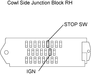
Remove the STOP SW fuse and IGN fuse from the cowl side junction block RH.
-
Measure the resistance according to the value(s) in the table below.
Standard Resistance Tester Connection Condition Specified Condition STOP SW fuse Always Below 1 Ω IGN fuse Always Below 1 Ω -
Reinstall the STOP SW fuse and IGN fuse.
NG
REPLACE FUSE (STOP SW AND IGN FUSE)
OK
REPAIR OR REPLACE HARNESS OR CONNECTOR (STOP LIGHT SWITCH POWER SOURCE)
-