SFI SYSTEM, Diagnostic DTC:P1235, P1236

| DTC Code | DTC Name |
|---|---|
| P1235 | High Pressure Fuel Pump Circuit |
| P1236 | High Pressure Fuel Pump No. 2 Circuit |
DESCRIPTION
The fuel pump for high pressure is attached to the insulator, which is attached to the cylinder head cover. The pump activates according to the position of the cam on the intake side camshaft (bank 1 and bank 2).
The fuel pump for high pressure increases the pressure of the fuel supplied from the fuel pump in the fuel tank to 4 to 13 MPa (40.8 to 132.6 kgf/cm2, 580 to 1885 psi) according to the operating condition, and it feeds the fuel to the fuel delivery pipe.
| DTC No. | DTC Detection Condition | Trouble Area |
|---|---|---|
| P1235 | Open or short in fuel pump for high pressure (bank 1) circuit for 1 second or more (1 trip detection logic) |
|
| P1236 | Open or short in fuel pump for high pressure (bank 2) circuit for 1 second or more (1 trip detection logic) |
|
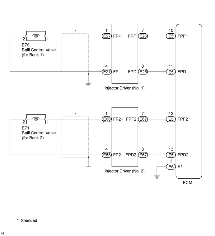
WIRING DIAGRAM
INSPECTION PROCEDURE
Tech Tips
Read freeze frame data using the intelligent tester. Freeze frame data records the engine condition when malfunctions are detected. When troubleshooting, freeze frame data can help determine if the vehicle was moving or stationary, if the engine was warmed up or not, if the air fuel ratio was lean or rich, and other data from the time the malfunction occurred.
PROCEDURE
-
CHECK FOR DTC
-
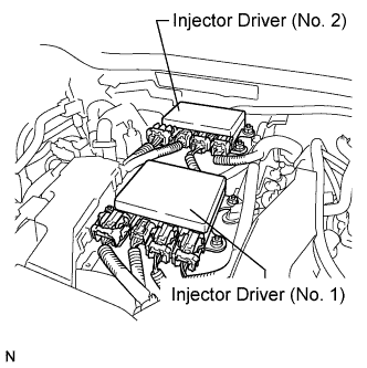
Interchange the injector driver No. 1 and No. 2 Click here.
-
Connect the intelligent tester to the DLC3.
-
Turn the engine switch on (IG) and turn the tester ON.
-
Clear DTCs Click here.
Note
Before clearing the DTCs, write them down.
-
Start the engine.
-
Enter the following menus: Powertrain / Engine / DTC.
-
Read the DTC.
Result Display (DTC Output) Proceed to DTCs do not change A DTCs change (change in malfunctioning cylinder or EDU code) B
B 
REPLACE INJECTOR DRIVER Click here
A 
-
-
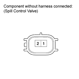
INSPECT SPILL CONTROL VALVE
-
Disconnect the spill control valve connector.
-
Measure the resistance according to the value(s) in the table below.
Standard Resistance Tester Connection Condition Specified Condition 1 - 2 20°C (68°F) 1.19 to 1.39 Ω -
Reconnect the spill control valve connector.
NG
REPLACE FUEL PUMP FOR HIGH PRESSURE Click here
OK
-
-
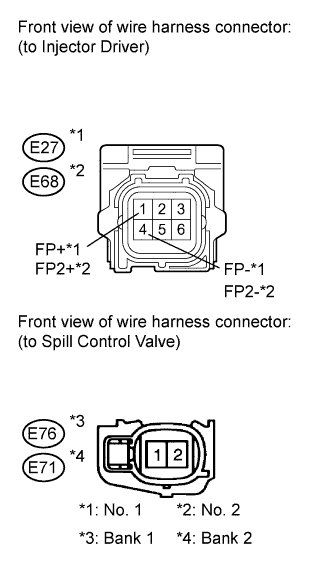
CHECK HARNESS AND CONNECTOR (INJECTOR DRIVER - SPILL CONTROL VALVE)
-
Disconnect the injector driver connector.
-
Disconnect the spill control valve connector.
-
Measure the resistance according to the value(s) in the table below.
Standard Resistance (Check for Open) Injector Driver (No. 1) Tester Connection Condition Specified Condition E27-1 (FP+) - E76-1 Always Below 54 mΩ E27-4 (FP-) - E76-2 Always Below 54 mΩ Injector Driver (No. 2) Tester Connection Condition Specified Condition E68-1 (FP2+) - E71-1 Always Below 54 mΩ E68-4 (FP2-) - E71-2 Always Below 54 mΩ Standard Resistance (Check for Short) Injector Driver (No. 1) Tester Connection Condition Specified Condition E27-1 (FP+) or E76-1 - Engine ground Always 10 kΩ or more E27-4 (FP-) or E76-2 - Engine ground Always 10 kΩ or more Injector Driver (No. 2) Tester Connection Condition Specified Condition E68-1 (FP2+) or E71-1 - Engine ground Always 10 kΩ or more E68-4 (FP2-) or E71-2 - Engine ground Always 10 kΩ or more -
Reconnect the injector driver connector and spill control valve connector.
NG
REPAIR OR REPLACE HARNESS OR CONNECTOR (INJECTOR DRIVER - SPILL CONTROL VALVE)
OK
-
-
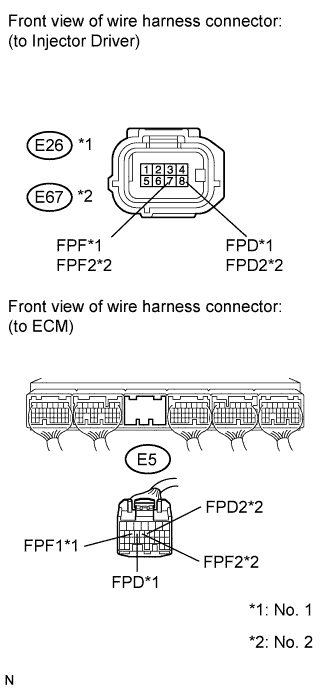
CHECK HARNESS AND CONNECTOR (INJECTOR DRIVER - ECM)
-
Disconnect the injector driver (No. 1) connector.
-
Disconnect the injector driver (No. 2) connector.
-
Disconnect the ECM connector.
-
Measure the resistance according to the value(s) in the table below.
Standard Resistance (Check for Open) Tester Connection Condition Specified Condition E26-8 (FPD) - E5-11 (FPD) Always Below 1 Ω E26-7 (FPF) - E5-10 (FPF) Always Below 1 Ω E67-8 (FPD2) - E5-13 (FPD2) Always Below 1 Ω E67-7 (FPF2) - E5-12 (FPF2) Always Below 1 Ω Standard Resistance (Check for Short) Tester Connection Condition Specified Condition E26-8 (FPD) or E5-11 (FPD) - Body ground Always 10 kΩ or higher E26-7 (FPF) or E5-10 (FPF1) - Body ground Always 10 kΩ or higher E67-8 (FPD2) or E5-13 (FPD2) - Body ground Always 10 kΩ or higher E67-7 (FPF2) or E5-12 (FPF2) - Body ground Always 10 kΩ or higher -
Reconnect the injector driver connectors and ECM connector.
NG
REPAIR OR REPLACE HARNESS OR CONNECTOR (INJECTOR DRIVER - ECM)
OK 
REPLACE ECM Click here
-