SFI SYSTEM, Diagnostic DTC:P0201, P0202, P0203, P0204, P0205, P0206, P0207, P0208, P062D, P062E

| DTC Code | DTC Name |
|---|---|
| P0201 | Injector Circuit / Open - (Cylinder 1) |
| P0202 | Injector Circuit / Open - (Cylinder 2) |
| P0203 | Injector Circuit / Open - (Cylinder 3) |
| P0204 | Injector Circuit / Open - (Cylinder 4) |
| P0205 | Injector Circuit / Open - (Cylinder 5) |
| P0206 | Injector Circuit / Open - (Cylinder 6) |
| P0207 | Injector Circuit / Open - (Cylinder 7) |
| P0208 | Injector Circuit / Open - (Cylinder 8) |
| P062D | No. 1 Fuel Injector Driver Circuit Performance |
| P062E | No. 2 Fuel Injector Driver Circuit Performance |
DESCRIPTION
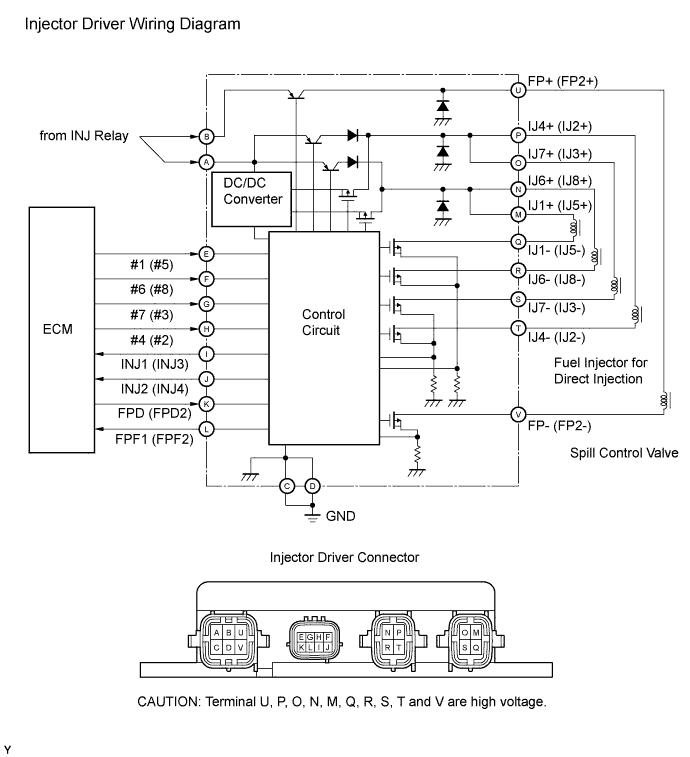
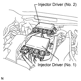
The D-4S system has two fuel injection methods. One is the in-cylinder direct injection method that directly injects pressurized fuel into the combustion chamber. The other is the intake port injection method. The ECM determines which fuel injection method to use in accordance with the engine conditions. For the in-cylinder direction injection method, the 2 injector drivers in the engine room operate the fuel injectors (for direct injection) at high speeds.
Each injector driver receives fuel injection request signals from the ECM and converts the signals to high voltage / high current injector operation signals to operate the fuel injectors (for direct injection). The fuel injection sequence occurs in the following order: No.1, No. 8, No. 7, No. 3, No. 6, No. 5, No. 4, No. 2. The ECM monitors each injector driver at all times. If drivers or injectors are malfunctioning, the injector driver sends fuel injector operation condition fail signals (INJ1 to INJ4) to the ECM. When the ECM receives the signals, the ECM stops the fuel injection control of the appropriate cylinders, cuts voltage to the appropriate INJ relay, and illuminates the MIL.
| INJ No. | Injector Driver Group | Fuel Injector Group |
|---|---|---|
| INJ1 | Injector Driver (No. 1) |
|
| INJ2 |
|
|
| INJ3 | Injector Driver (No. 2) |
|
| INJ4 |
|
| DTC No. | DTC Detection Condition | Trouble Area |
|---|---|---|
| P0201 | Either of following is detected (1 trip detection logic):
|
|
| P0202 | Either of following is detected (1 trip detection logic):
|
|
| P0203 | Either of following is detected (1 trip detection logic):
|
|
| P0204 | Either of following is detected (1 trip detection logic):
|
|
| P0205 | Either of following is detected (1 trip detection logic):
|
|
| P0206 | Either of following is detected (1 trip detection logic):
|
|
| P0207 | Either of following is detected (1 trip detection logic):
|
|
| P0208 | Either of following is detected (1 trip detection logic):
|
|
| P062D | INJ1 and INJ2 signals are not input for 60 consecutive revolutions (1 trip detection logic) | |
| P062E | INJ3 and INJ4 signals are not input for 60 consecutive revolutions (1 trip detection logic) |
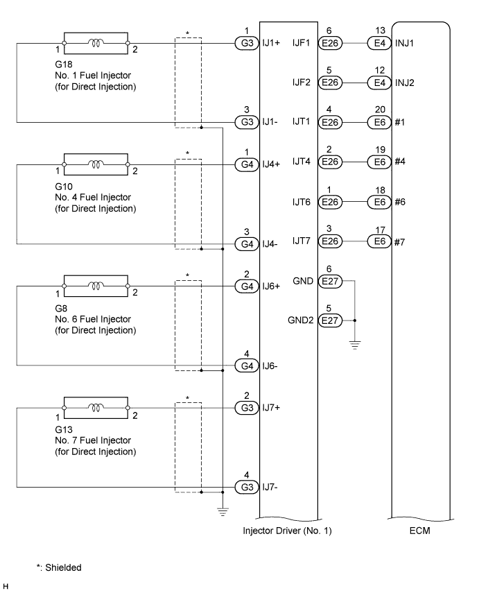
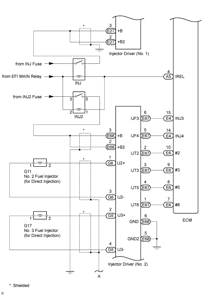
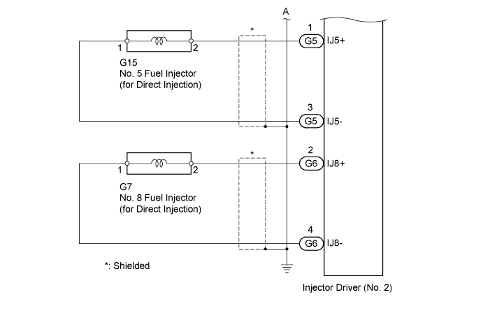
WIRING DIAGRAM
INSPECTION PROCEDURE
Tech Tips
-
If the current from the INJ relay is cut because DTC P062D is stored, DTC P1235 will be stored even if the fuel pump for high pressure (Bank 1) is normal.
-
If the current from the INJ2 relay is cut because DTC P062E is stored, DTC P1236 will be stored even if the fuel pump fir high pressure (Bank 2) is normal.
-
Read freeze frame data using the intelligent tester. The ECM records vehicle and driving condition information as freeze frame data the moment a DTC is stored. When troubleshooting, freeze frame data can help determine if the vehicle was moving or stationary, if the engine was warmed up or not, if the air fuel ratio was lean or rich, and other data from the time the malfunction occurred.
PROCEDURE
-
CLEAR DTC
-
Connect the intelligent tester to the DLC3.
-
Turn the engine switch on (IG).
-
Turn the tester on.
-
Clear the DTCs Click here.
Tech Tips
-
If DTC P062D is stored, current to the INJ relay will be shut off.
-
If DTC P062E is stored, current to the INJ2 relay will be shut off.
-
NEXT 
-
-
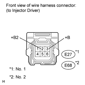
INSPECT INJECTOR DRIVER (POWER SOURCE OF ECU)
-
Disconnect the injector driver connectors.
-
Turn the engine switch on (IG).
-
Measure the voltage according to the value(s) in the table below.
Standard Voltage (No. 1) Tester Connection Switch Condition Specified Condition E27-3 (+B) - Engine ground Engine switch on (IG) 11 to 14 V E27-2 (+B2) - Engine ground Engine switch on (IG) 11 to 14 V Standard Voltage (No. 2) Tester Connection Switch Condition Specified Condition E68-3 (+B) - Engine ground Engine switch on (IG) 11 to 14 V E68-2 (+B2) - Engine ground Engine switch on (IG) 11 to 14 V Result Result Proceed To OK A NG (for injector driver No. 1) B NG (for injector driver No. 2) C -
Reconnect the injector driver connectors.
B 
INSPECT FUSE (INJ FUSE) Click here
C
CHECK FUSE (INJ2 FUSE) Click here
A
-
-
CHECK HARNESS AND CONNECTOR (GROUND CIRCUIT)
-
Disconnect injector driver connector.
-
Measure the resistance according to the value(s) in the table below.
Standard Resistance (No. 1) Tester Connection Condition Specified Condition E27-6 (GND) - Body ground Always Below 1 Ω E27-5 (GND2) - Body ground Always Below 1 Ω Standard Resistance (No. 2) Tester Connection Condition Specified Condition E68-6 (GND) - Body ground Always Below 1 Ω E68-5 (GND2) - Body ground Always Below 1 Ω -
Reconnect the injector driver connector.
NG 
REPAIR OR REPLACE HARNESS OR CONNECTOR (GROUND CIRCUIT)
OK
-
-
CHECK FOR DTC
-
Interchange the injector driver No. 1 and No. 2.
-
Connect the intelligent tester to the DLC3.
-
Turn the engine switch on (IG) and turn the tester on.
-
Clear the DTCs Click here.
Note
Before clearing the DTCs, write them down.
-
Start the engine.
-
Enter the following menus: Powertrain / Engine / DTC.
-
Read the DTC.
Result Display (DTC Output) Proceed to DTCs do not change A DTCs change (change in malfunctioning cylinder or injector driver code) B
B
REPLACE INJECTOR DRIVER Click here
A
-
-
CHECK HARNESS AND CONNECTOR (FUEL INJECTOR FOR DIRECT INJECTION)
-
Disconnect the injector driver (No. 1) connector.
-
Disconnect the injector driver (No. 2) connector.
-
Measure the resistance according to the value(s) in the table below.
Standard Resistance (No. 1) Tester Connection Condition Specified Condition G3-1 (IJ1+) - G3-3 (IJ1-) 20°C (68°F) 2.01 to 2.43 Ω G4-1 (IJ4+) - G4-3 (IJ4-) 20°C (68°F) 2.01 to 2.43 Ω G4-2 (IJ6+) - G4-4 (IJ6-) 20°C (68°F) 2.01 to 2.43 Ω G3-2 (IJ7+) - G3-4 (IJ7-) 20°C (68°F) 2.01 to 2.43 Ω Standard Resistance (No. 2) Tester Connection Condition Specified Condition G6-1 (IJ2+) - G6-3 (IJ2-) 20°C (68°F) 2.01 to 2.43 Ω G5-2 (IJ3+) - G5-4 (IJ3-) 20°C (68°F) 2.01 to 2.43 Ω G5-1 (IJ5+) - G5-3 (IJ5-) 20°C (68°F) 2.01 to 2.43 Ω G6-2 (IJ8+) - G6-4 (IJ8-) 20°C (68°F) 2.01 to 2.43 Ω -
Reconnect the injector driver connectors.
NG
INSPECT FUEL INJECTOR FOR DIRECT INJECTION Click here
OK
-
-
CHECK HARNESS AND CONNECTOR (INJECTOR DRIVER - ECM)
-
Disconnect the ECM connectors.
-
Disconnect the injector driver connector.
-
Measure the resistance according to the value(s) in the table below.
Standard Resistance (Check for Open) Tester Connection Condition Specified Condition E26-6 (IJF1) - E4-13 (INJ1) Always Below 1 Ω E26-5 (IJF2) - E4-12 (INJ2) Always Below 1 Ω E67-6 (IJF3) - E4-15 (INJ3) Always Below 1 Ω E67-5 (IJF4) - E4-14 (INJ4) Always Below 1 Ω E26-4 (IJT1) - E6-20 (#1) Always Below 1 Ω E67-2 (IJT2) - E6-10 (#2) Always Below 1 Ω E67-3 (IJT3) - E6-9 (#3) Always Below 1 Ω E26-2 (IJT4) - E6-19 (#4) Always Below 1 Ω E67-4 (IJT5) - E6-8 (#5) Always Below 1 Ω E26-1 (IJT6) - E6-18 (#6) Always Below 1 Ω E26-3 (IJT7) - E6-17 (#7) Always Below 1 Ω E67-1 (IJT8) - E6-7 (#8) Always Below 1 Ω Standard Resistance (Check for Short) Tester Connection Condition Specified Condition E26-6 (IJF1) or E4-13 (INJ1) - Body ground Always 10 kΩ or higher E26-5 (IJF2) or E4-12 (INJ2) - Body ground Always 10 kΩ or higher E67-6 (IJF3) or E4-15 (INJ3) - Body ground Always 10 kΩ or higher E67-5 (IJF4) or E4-14 (INJ4) - Body ground Always 10 kΩ or higher E26-4 (IJT1) or E6-20 (#1) - Body ground Always 10 kΩ or higher E67-2 (IJT2) or E6-10 (#2) - Body ground Always 10 kΩ or higher E67-3 (IJT3) or E6-9 (#3) - Body ground Always 10 kΩ or higher E26-2 (IJT4) or E6-19 (#4) - Body ground Always 10 kΩ or higher E67-4 (IJT5) or E6-8 (#5) - Body ground Always 10 kΩ or higher E26-1 (IJT6) or E6-18 (#6) - Body ground Always 10 kΩ or higher E26-3 (IJT7) or E6-17 (#7) - Body ground Always 10 kΩ or higher E67-1 (IJT8) or E6-7 (#8) - Body ground Always 10 kΩ or higher -
Reconnect the injector driver connector and ECM connectors.
NG
REPAIR OR REPLACE HARNESS OR CONNECTOR (INJECTOR DRIVER - ECM)
OK 
REPLACE ECM Click here
-
-
INSPECT FUSE (INJ FUSE)
-
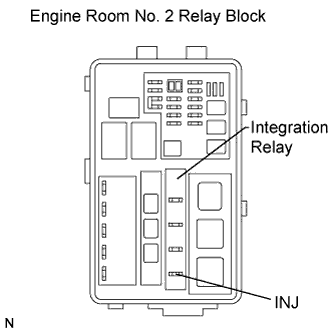
Remove the INJ fuse from the integration relay.
-
Measure the resistance according to the value(s) in the table below.
Standard Resistance Tester Connection Condition Specified Condition INJ fuse Always Below 1 Ω -
Reinstall the INJ fuse.
NG
REPLACE FUSE (INJ FUSE)
OK
-
-
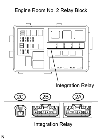
INSPECT INTEGRATION RELAY (INJ RELAY)
-
Remove the integration relay from the engine room No. 2 relay block.
-
Measure the resistance according to the value(s) in the table below.
Standard Resistance Tester Connection Condition Specified Condition 2C-1 - 2A-4 When no battery voltage applied to terminals 2A-3 and 2A-1 10 kΩ or higher When battery voltage applied to terminals 2A-3 and 2A-1 Below 1 Ω -
Reinstall the integration relay.
NG
REPLACE INTEGRATION RELAY (INJ RELAY) Click here
OK
-
-
CHECK HARNESS AND CONNECTOR (INJ RELAY - EFI MAIN RELAY)
-
Remove the integration relay from the engine room No. 2 relay block.
-
Measure the resistance according to the value(s) in the table below.
Standard Resistance Tester Connection Condition Specified Condition 2A-8 - 2A-1 Always Below 1 Ω -
Reinstall the integration relay.
NG
REPAIR OR REPLACE HARNESS OR CONNECTOR (EFI NO. 2 FUSE - INJ RELAY)
OK
-
-
CHECK HARNESS AND CONNECTOR (INJ RELAY - ECM)
-
Remove the integration relay from the engine room No. 2 relay block.
-
Disconnect the ECM connector.
-
Measure the resistance according to the value(s) in the table below.
Standard Resistance Tester Connection Condition Specified Condition INJ Relay (2A-3) - A5-4 (IREL) Always Below 1 Ω -
Reinstall the integration relay.
-
Reconnect the ECM Connector.
NG
REPAIR OR REPLACE HARNESS OR CONNECTOR (INJ RELAY - ECM)
OK
REPAIR OR REPLACE HARNESS OR CONNECTOR (INJ RELAY - P/I-B FUSE)
-
-
INSPECT FUEL INJECTOR FOR DIRECT INJECTION
-
Check the resistance of the fuel injector for direct injection Click here
NG
REPLACE FUEL INJECTOR FOR DIRECT INJECTION Click here
OK
REPAIR OR REPLACE HARNESS OR CONNECTOR (INJECTOR DRIVER - ECM)
-
-
CHECK FUSE (INJ2 FUSE)
-
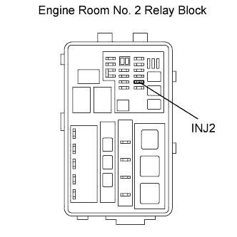
Remove the INJ2 fuse from the engine room No. 2 relay block.
-
Measure the resistance according to the value(s) in the table below.
Standard Resistance Tester Connection Condition Specified Condition INJ2 fuse Always Below 1 Ω -
Reinstall the INJ2 fuse.
NG
REPLACE FUSE (INJ2 FUSE)
OK
-
-
INSPECT RELAY (INJ2 RELAY)
-
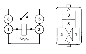
Remove the INJ2 relay from the engine room No. 2 relay block.
-
Measure the resistance according to the value(s) in the table below.
Standard Resistance Tester Connection Condition Specified Condition 3 - 5 When no battery voltage applied to terminals 1 and 2 10 kΩ or higher When battery voltage applied to terminals 1 and 2 Below 1 Ω -
Reinstall the INJ2 relay.
NG
REPLACE RELAY (INJ2 RELAY)
OK
-
-
CHECK HARNESS AND CONNECTOR (INJ2 RELAY POWER SOURCE)
-
Remove the INJ2 relay from the engine room No. 2 relay block.
-
Turn the engine switch on (IG).
-
Measure the voltage according to the value(s) in the table below.
Standard Voltage Tester Connection Switch Condition Specified Condition INJ2 relay (2) - Body ground Engine switch on (IG) 11 to 14 V -
Reinstall the INJ2 relay.
NG
REPAIR OR REPLACE HARNESS OR CONNECTOR (INJ2 RELAY - EFI MAIN RELAY)
OK
-
-
CHECK HARNESS AND CONNECTOR (INJ2 RELAY - ECM)
-
Remove the INJ2 relay from the engine room No. 2 relay block.
-
Disconnect the ECM connector.
-
Measure the resistance according to the value(s) in the table below.
Standard Resistance Tester Connection Condition Specified Condition INJ2 relay (1) - A5-4 (IREL) Always Below 1 Ω -
Reinstall the INJ2 relay.
-
Reconnect the ECM connector.
NG
REPAIR OR REPLACE HARNESS OR CONNECTOR (INJ2 RELAY - ECM)
OK
-
-
CHECK HARNESS AND CONNECTOR (INJ2 RELAY - BATTERY)
-
Remove the INJ2 relay from the engine room No. 2 relay block.
-
Turn the engine switch on (IG).
-
Measure the voltage according to the value(s) in the table below.
Standard Voltage Tester Connection Switch Condition Specified Condition INJ2 relay (2) - Body ground Engine switch on (IG) 11 to 14 V -
Reinstall the INJ2 relay.
NG
REPAIR OR REPLACE HARNESS OR CONNECTOR (INJ2 RELAY - BATTERY)
OK
REPAIR OR REPLACE HARNESS OR CONNECTOR (INJ2 RELAY - INJECTOR DRIVER (NO. 2))
-