SFI SYSTEM, Diagnostic DTC:P0335, P0337, P0338, P0339

| DTC Code | DTC Name |
|---|---|
| P0335 | Crankshaft Position Sensor "A" Circuit |
| P0337 | Crankshaft Position Sensor "A" Circuit Low Input |
| P0338 | Crankshaft Position Sensor "A" Circuit High Input |
| P0339 | Crankshaft Position Sensor "A" Circuit Intermittent |
DESCRIPTION
The crankshaft position sensor system consists of a crank angle sensor plate and magnetic resistance element type sensor. The crank angle sensor plate has 34 teeth at 10° intervals (2 teeth are missing for detecting top dead center), and is installed to the rear end of the crankshaft. The crank position sensor outputs 34 rotation signals per engine revolution. The ECM uses the G2 signal to distinguish between the cylinders, and uses the NE signal to detect the crankshaft position and engine speed.
| DTC No. | DTC Detection Condition | Trouble Area |
|---|---|---|
| P0335 |
|
|
| P0337 | Output voltage of Crankshaft position sensor 0.3 V or less for 4 seconds (1 trip detection logic) |
|
| P0338 | Output voltage of crankshaft position sensor 4.7 V or more for 4 seconds (1 trip detection logic) |
|
| P0339 | Under conditions (a), (b) and (c), no crankshaft position sensor signal to ECM for 0.05 seconds or more (1 trip detection logic): (a) Engine speed 1000 rpm or more (b) Starter signal OFF (c) 3 seconds or more have lapsed since starter signal switched from ON to OFF |
|
-
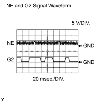
Reference: Inspection using an oscilloscope.
Tech Tips
-
The correct waveform is as shown.
-
The wavelength becomes shorter as the engine speed increases.
-
G2+ and G2- stand for the camshaft position sensor signal, and NE+ stands for the crankshaft position sensor signal.
Item Content Terminal NE+ - NE-
G2+ - G2-
Equipment Setting 5 V/DIV., 20 msec./DIV. Condition Cranking or idling -
MONITOR DESCRIPTION
If there is no signal from the crankshaft position sensor despite the engine revolving, the ECM interprets this as a malfunction of the sensor.
When the sensor output voltage remains less than 0.3 V, or more than 4.7 V for more than 4 seconds, the ECM sets a DTC.
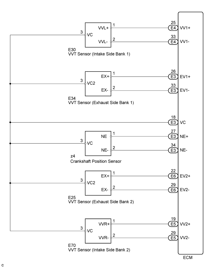
WIRING DIAGRAM
INSPECTION PROCEDURE
Tech Tips
-
If no problem is found by this diagnostic troubleshooting procedure, troubleshooting the engine mechanical system.
-
Check the engine speed. The engine speed can be checked by using the intelligent tester. To check, follow the operation below:
-
Connect the intelligent tester to the DLC3.
-
Start the engine.
-
Turn the tester ON.
-
Enter the following menus: Powertrain / Engine / Data List / All Data / Engine Speed.
-
The engine speed may be indicated as zero despite the engine revolving normally. This is caused by a lack of NE signals from the crankshaft position sensor. Alternatively, the engine speed may be indicated as lower than the actual engine speed, if the crankshaft position sensor output voltage is insufficient.
-
Read freeze frame data using the intelligent tester. Freeze frame data records the engine conditions when malfunctions are detected. When troubleshooting, freeze frame data can help determine if the vehicle was running or stopped, if the engine was warmed up or not, if the air fuel ratio was lean or rich, and other data from the time the malfunction occurred.
PROCEDURE
-
READ VALUE USING INTELLIGENT TESTER (ENGINE SPEED)
-
Connect the intelligent tester to the DLC3.
-
Turn the engine switch on (IG) and turn the tester ON.
-
Enter the following menus: Powertrain / Engine / Data List / All Data / Engine Speed.
-
Star the engine.
-
Read the values displayed on the tester while the engine is running.
Standard Correct values are displayed. Tech Tips
-
To check the engine speed change, display the graph on the tester.
-
If the engine does not start, check the engine speed while cranking.
-
If the engine speed indicated on the tester remains zero (0), there may be an open or short in the crankshaft position sensor circuit.
Result Result Proceed to NG A OK B
-
B 
CHECK FOR INTERMITTENT PROBLEMS Click here
A 
-
-
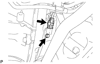
INSPECT CRANKSHAFT POSITION SENSOR (SENSOR POWER SOURCE)
-
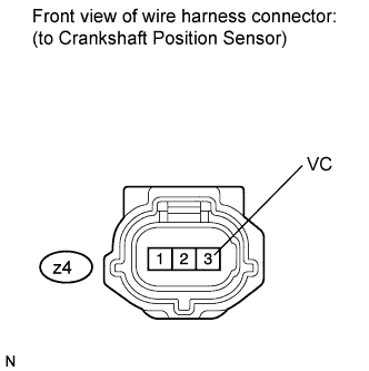
Disconnect the crankshaft position sensor connector.
-
Measure the voltage according to the value(s) in the table below.
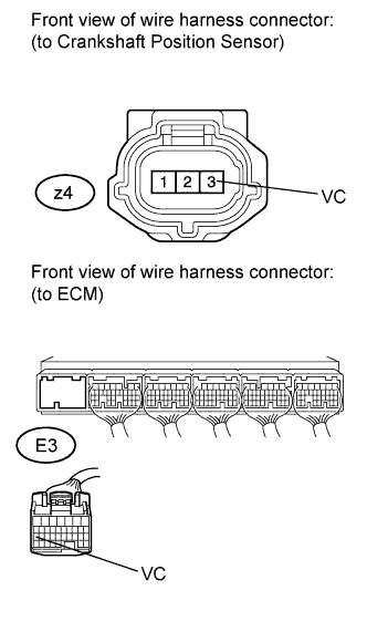
Standard Voltage Tester Connection Switch Condition Specified Condition z4-3 (VC) - Body ground Engine switch on (IG) 4.5 to 5.0 V -
Reconnect the crankshaft position sensor connector.
NG 
CHECK HARNESS AND CONNECTOR (CRANKSHAFT POSITION SENSOR - ECM) Click here
OK
-
-
CHECK HARNESS AND CONNECTOR (CRANKSHAFT POSITION SENSOR - ECM)
-
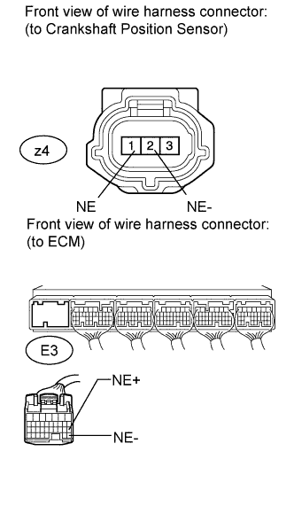
Disconnect the crankshaft position sensor connector.
-
Disconnect the ECM connector.
-
Measure the resistance according to the value(s) in the table below.
Standard Resistance (Check for Open) Tester Connection Condition Specified Condition z4-1 (NE) - E3-27 (NE+) Always Below 1 Ω z4-2 (NE-) - E3-34 (NE-) Always Below 1 Ω Standard Resistance (Check for Short) Tester Connection Condition Specified Condition z4-1 (NE) or E3-27 (NE+) - Body ground Always 10 kΩ or higher z4-2 (NE-) or E3-34 (NE-) - Body ground Always 10 kΩ or higher -
Reconnect the crankshaft position sensor connector and ECM connector.
NG
REPAIR OR REPLACE HARNESS OR CONNECTOR
OK
-
-
CHECK SENSOR INSTALLATION (CRANKSHAFT POSITION SENSOR)
-
Check the crankshaft position sensor installation.
OK Sensor is installed correctly.
NG
REPAIR OR REPLACE CRANKSHAFT POSITION SENSOR Click here
OK
-
-
CHECK CRANKSHAFT POSITION SENSOR PLATE (TEETH OF SENSOR PLATE)
-
Check the teeth of the sensor plate.
OK Sensor plate does not have any crack or deformation.
NG
REPLACE CRANKSHAFT ANGLE SENSOR ROTOR Click here
OK
-
-
REPLACE CRANKSHAFT POSITION SENSOR
-
Replace the crankshaft position sensor Click here.
NEXT
-
-
CHECK WHETHER DTC OUTPUT RECURS (DTC P0335, P0337, P0338 AND/OR P0339)
-
Connect the intelligent tester to the DLC3.
-
Turn the engine switch on (IG).
-
Turn the tester ON.
-
Clear the DTCs Click here.
-
Start the engine.
-
Enter the following menus: Powertrain / Engine / DTC.
-
Read the DTCs.
Result Result Proceed to DTC is not output A DTC P0335, P0337, P0338 and/or P0339 are output B Tech Tips
If the engine does not start, replace the ECM.
B
REPLACE ECM Click here
A 
END
-
-
CHECK HARNESS AND CONNECTOR (CRANKSHAFT POSITION SENSOR - ECM)
-
Disconnect the crankshaft position sensor connector.
-
Disconnect the ECM connector.
-
Measure the resistance according to the value(s) in the table below.
Standard Resistance (Check for Open) Tester Connection Condition Specified Condition z4-3 (VC) - E3-18 (VC) Always Below 1 Ω Standard Resistance (Check for Short) Tester Connection Condition Specified Condition z4-3 (VC) or E3-18 (VC) - Body ground Always 10 kΩ or higher -
Reconnect the crankshaft position sensor connector and ECM connector.
NG
REPAIR OR REPLACE HARNESS OR CONNECTOR
OK
REPLACE ECM Click here
-