SFI SYSTEM FREEZE FRAME DATA

-
DESCRIPTION
-
The ECM records vehicle and driving condition information as freeze frame data the moment a DTC is stored. When troubleshooting, freeze frame data can be helpful in determining whether the vehicle was running or stopped, whether the engine was warmed up or not, whether the air fuel ratio was lean or rich, as well as other data recorded at the time of a malfunction.
Tech Tips
If it is impossible to replicate the problem even though a DTC is detected, confirm the freeze frame data.
-
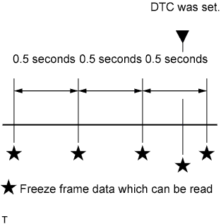
The ECM records engine conditions in the form of freeze frame data every 0.5 seconds. Using the intelligent tester, five separate sets of freeze frame data, including the data values at the time when the DTC was set, can be checked.
-
3 data sets before the DTC was set.
-
1 data set when the DTC was set.
-
1 data set after the DTC was set.
-
These data sets can be used to simulate the condition of the vehicle around the time of the occurrence of the malfunction. The data may assist in identifying of the cause of the malfunction, and in judging whether it was temporary or not.
-
-
LIST OF FREEZE FRAME DATA
LABEL
(Tester Display)
Measurement Item Diagnostic Note Injector (Port) Injector - IGN Advance Ignition advance - Calculate Load Calculate load Calculated load by ECM Vehicle Load Vehicle load Load percentage in terms of maximum intake air flow amount MAF Mass air flow volume If value approximately 0.0 g/sec.:
-
Mass air flow meter power source circuit open or short
-
VG circuit open or short
If value 160.0 g/sec. or more:
-
E2G circuit open
Engine Speed Engine speed - Vehicle Speed Vehicle speed Speed indicated on speedometer Coolant Temp Engine coolant temperature If value -40°C (-40°F), sensor circuit open
If value 140°C (284°F), sensor circuit shorted
Intake Air Intake air temperature If value -40°C (-40°F), sensor circuit open
If value 140°C (284°F), sensor circuit shorted
Fuel Press Fuel Pressure - Air-Fuel Ratio Air fuel ratio - Purge Density Learn Value Learning value of purge density - Evap Purge Flow Purge flow - EVAP (Purge) VSV EVAP purge VSV duty ratio - Knock correct Learn Value Correction learning value of knocking - Knock Feedback Value Feedback value of knocking - ECT Lock Up ECT lock up status - Accelerator Pedal Position No.1 Accelerator Pedal Position No. 1 - Accelerator Pedal Position No.2 Accelerator pedal position No. 2 - Throttle Position Absolute throttle position Read value with engine switch on (IG) (Do not start engine) Throttle Sensor Position Throttle sensor positioning Read value with engine switch on (IG) (Do not start engine) Throttle Sensor Position #2 Absolute throttle sensor positioning #2 - Throttle Motor Throttle actuator - O2S B1 S2 Heated oxygen sensor output voltage Performing Control the Injection Volume or Control the Injection Volume for A/F sensor function of Active Test enables technician to check output voltage of sensor O2S B2 S2 Heated oxygen sensor output voltage Performing Control the Injection Volume or Control the Injection Volume for A/F sensor function of Active Test enables technician to check output voltage of sensor AFS B1 S1 Air fuel ratio sensor output voltage Performing Control the Injection Volume or Control the Injection Volume for A/F sensor function of Active Test enables technician to check output voltage of sensor AFS B2 S1 Air fuel ratio sensor output voltage Performing Control the Injection Volume or Control the Injection Volume for A/F sensor function of Active Test enables technician to check output voltage of sensor AFS B2 S1 Air fuel ratio sensor output current Performing Control the Injection Volume or Control the Injection Volume for A/F sensor function of Active Test enables technician to check current output of sensor Total FT #1 Total fuel trim (bank 1) - Total FT #2 Total fuel trim (bank 2) - Short FT #1 Short-term fuel trim (bank 1) Short-term fuel compensation used to maintain air fuel ratio at stoichiometric air fuel ratio Long FT #1 Long-term fuel trim (bank 1) Overall fuel compensation carried out in long-term to compensate a continual deviation of short-term fuel trim from central valve Short FT #2 Short-term fuel trim (bank 2) Short-term fuel compensation used to maintain air fuel ratio at stoichiometric air fuel ratio Long FT #2 Long-term fuel trim (bank 2) Overall fuel compensation carried out in long-term to compensate a continual deviation of short-term fuel trim from central valve Fuel System Status (bank1) Fuel system status (bank 1)
-
OL (Open Loop): Has not yet satisfied conditions to go closed loop
-
CL (Closed Loop): Using heated oxygen sensor as feedback for fuel control
-
OLDrive: Open loop due to driving conditions (fuel enrichment)
-
OLFault: Open loop due to detected system fault
-
CLFault: Closed loop but heated oxygen sensor, which used for fuel control malfunctioning
Fuel System Status (bank2) Fuel system status (bank 2)
-
OL (Open Loop): Has not yet satisfied conditions to go closed loop
-
CL (Closed Loop): Using heated oxygen sensor as feedback for fuel control
-
OLDrive: Open loop due to driving conditions (fuel enrichment)
-
OLFault: Open loop due to detected system fault
-
CLFault: Closed loop but heated oxygen sensor, which used for fuel control malfunctioning
AF FT B1 S1 Fuel trim at air fuel ratio sensor - AFS B1 S1 Air fuel ratio sensor output current Performing Control the Injection Volume or Control the Injection Volume for A/F sensor function of Active Test enables technician to check current output of sensor AF FT B2 S1 Fuel trim at air fuel ratio sensor - Catalyst Temp (B1 S1) Catalyst temperature - Catalyst Temp (B2 S1) Catalyst temperature - Catalyst Temp (B1 S2) Catalyst temperature - Catalyst Temp (B2 S2) Catalyst temperature - Initial Engine Coolant Temp Initial engine coolant temperature - Initial Intake Air Temp Initial intake air temperature - Injection Volum (Cylinder 1) Injection volume - SPD (NO) Output shaft speed - Injection Timing (D4) Injection timing (D4) - Fuel Pump Duty (D4) Fuel pump duty (D4) - Injection Time (D4) Injection time (D4) - Fuel Pressure Target Value Target fuel pressure - HP FP Discharge Rate High pressure fuel pump discharge rate (bank 1) - Injection Switching Status Prohibition of changing the D-4S injection method - HP FP Discharge Rate 2 High pressure fuel pump discharge rate (bank 2) - Injection Way Injection mode - ACC Relay ACC relay status - Starter Relay Starter relay status - Starter Signal Starter signal - Starter Control Starter control - Closed Throttle Position SW Closed throttle position switch - A/C Signal A/C switch status - Neutral Position SW Signal Neutral position switch signal - Electrical Load Signal Electrical load signal - Stop Light Switch Stop light switch status - Immobiliser Communication Immobiliser Communication - Fuel Cut Condition Fuel cut condition - Battery Voltage Battery voltage - Atmosphere Pressure Atmospheric pressure - Fuel Pump Speed Control F/PMP relay status - EVAP Purge VSV Purge VSV VSV for EVAP controlled by ECM (ground side duty control) Fuel Pump Speed Status Fuel pump/speed status - Electric Fan Motor Fan motor status - ACIS VSV VSV for air intake control system - TC and TE1 TC and TE1 terminals of DLC3 - Engine Speed of Cyl #1 Engine speed for cylinder 1 - Engine Speed of Cyl #2 Engine speed for cylinder 2 - Engine Speed of Cyl #3 Engine speed for cylinder 3 - Engine Speed of Cyl #4 Engine speed for cylinder 4 - Engine Speed of Cyl #5 Engine speed for cylinder 5 - Engine Speed of Cyl #6 Engine speed for cylinder 6 - Engine Speed of Cyl #7 Engine speed for cylinder 7 - Engine Speed of Cyl #8 Engine speed for cylinder 8 - Av Engine Speed of All Cyl Engine speed for all cylinders - VVT Change Angle (Bank1) VVT change angle (bank 1) - VVT Ex Hold Lrn Val (Bank1) VVT exhaust hold duty ratio learning value (bank 1) - VVT Ex Chg Angle (Bank1) VVT exhaust change angle (bank 1) - VVT Ex OCV Duty (Bank1) VVT exhaust camshaft timing oil control valve duty (bank 1) - VVT Change Angle (Bank2) VVT change angle (bank 2) - VVT Ex Hold Lrn Val (Bank2) VVT exhaust hold duty ratio learning value (bank 2) - VVT Ex Chg Angle (Bank2) VVT exhaust change angle (bank 2) - VVT Ex OCV Duty (Bank2) VVT exhaust camshaft timing oil control valve duty (bank 2) - VVT-iE Aim Angle (Bank1) VVT-iE aim angle (bank 1) - VVT-iE Aim Angle (Bank2) VVT-iE aim angle (bank 2) - VVT-iE MOT Direction B1 VVT-iE motor detection (bank 1) - VVT-iE MOT Direction B2 VVT-iE motor detection (bank 2) - Idle Fuel Cut Idle fuel cut ON: when throttle valve fully closed and engine speed over 1500 rpm FC TAU FC TAU Fuel cut being performed under very light load to prevent engine combustion from becoming incomplete Shift SW Status (R Range) Park/neutral position switch status - Shift SW Status (P Range) Park/neutral position switch status - Shift SW Status (N Range) Park/neutral position switch status - Shift SW Status (D Range) Park/neutral position switch status - Sports Shift Up SW Sports shift up switch status - Sports Shift Down SW Sports shift down switch status - Sports Mode Selection SW Sports mode select switch status - Pattern Switch (PWR/M) Pattern switch (PWR) status - Kick Down Switch Status Kick down switch status - A/T Oil Temperature 1 A/T oil temperature - Snow Switch Status Pattern switch (ECT SNOW) status - Ignition Ignition counter to calculated misfire rate - Cylinder #1 Misfire Count Misfire ratio of cylinder 1 This item displayed only when idling Cylinder #2 Misfire Count Misfire ratio of cylinder 2 This item displayed only when idling Cylinder #3 Misfire Count Misfire ratio of cylinder 3 This item displayed only when idling Cylinder #4 Misfire Count Misfire ratio of cylinder 4 This item displayed only when idling Cylinder #5 Misfire Count Misfire ratio of cylinder 5 This item displayed only when idling Cylinder #6 Misfire Count Misfire ratio of cylinder 6 This item displayed only when idling Cylinder #7 Misfire Count Misfire ratio of cylinder 7 This item displayed only when idling Cylinder #8 Misfire Count Misfire ratio of cylinder 8 This item displayed only when idling All Cylinders Misfire Count All cylinders misfire count
Min. 0, Max. 255
- Misfire RPM Average of engine speed when misfire occurs
Min. 0 rpm, Max. 6375 rpm
- Misfire Load Average of engine load when misfire occurred
Min. 0 g/rev, Max. 3.98 g/rev
- Misfire Margin Margin to detect engine misfire
Min. -100%, Max. 99.22%
Misfire detection margin Received MIL from ECT MIL status from ECT - Shift Position Sig from ECT Shift Position from ECT - A/T Oil Temp from ECT A/T oil temperature from ECT - Engine Run Time Accumulated engine running time - Time after DTC Cleared Cumulative time after DTC cleared - Distance from DTC Cleared Accumulated distance after DTC cleared - Warmup Cycle Cleared DTC Warm-up cycle after DTC cleared - -