SFI SYSTEM, Diagnostic DTC:P0017, P0019

| DTC Code | DTC Name |
|---|---|
| P0017 | Crankshaft Position - Camshaft Position Correlation (Bank 1 Sensor B) |
| P0019 | Crankshaft Position - Camshaft Position Correlation (Bank 2 Sensor B) |
DESCRIPTION
Refer to DTC P0013 Click here.
| DTC No. | DTC Detection Condition | Trouble Area |
|---|---|---|
| P0017 | With engine warmed up and idling, valve timing on bank 1 exhaust side is deviated for 1 minute or more (2 trip detection logic) |
|
| P0019 | With engine warmed up and idling, valve timing on bank 2 exhaust side is deviated for 1 minute or more (2 trip detection logic) |
|
MONITOR DESCRIPTION
These DTCs are output when a valve timing deviation condition is detected. While the vehicle is being driven or the engine is idling (after the battery terminals are reconnected), if a valve timing deviation is detected during the valve timing initialization operation, it is determined that a malfunction has occurred. If this condition is detected while driving, a DTC is output (2 trip detection logic). However, if the valve timing is deviated, the camshaft position sensor malfunction DTC P1340 may be output.
A DTC is output if the following conditions are met: 1) the engine is idled, and then the engine switch is turned off; and 2) the engine is started and the engine is idled.
INSPECTION PROCEDURE
Tech Tips
Read freeze frame data using the intelligent tester. Freeze frame data records the engine condition when malfunctions are detected. When troubleshooting, freeze frame data can help determine if the vehicle was moving or stationary, if the engine was warmed up or not, if the air fuel ratio was lean or rich, and other data from the time the malfunction occurred.
PROCEDURE
-
CHECK ANY OTHER DTCS OUTPUT (IN ADDITION TO DTC P0017 OR P0019)
-
Connect the intelligent tester to the DLC3.
-
Turn the engine switch on (IG) and turn the tester ON.
-
Enter the following menus: Powertrain / Engine / Trouble Codes.
-
Read the DTCs.
Result Result Proceed to DTC P0017 or P0019 is output A DTC P0017 or P0019 and other DTCs are output B Tech Tips
If any DTCs other than P0017 or P0019 are output, troubleshoot those DTCs first.
B 
GO TO DTC CHART Click here
A 
-
-
PERFORM ACTIVE TEST USING INTELLIGENT TESTER (CONTROL THE VVT EXHAUST LINEAR)
Tech Tips
If the VVT system can be operated through the Active Test, it can be determined that there is no problem in the VVT system.
-
Connect the intelligent tester to the DLC3.
-
Turn the engine switch on (IG) and turn the tester ON.
-
Start the engine and warm it up.
-
Engine is idling.
-
Enter the following menus: Powertrain / Engine / Active Test / Control the VVT Exhaust Linear (Bank 1) or Control the VVT Exhaust Linear (Bank 2).
-
Check the engine speed while operating the oil control valve using the intelligent tester.
OK Tester Operation Engine Condition 0% Normal engine speed 100% Engine idles roughly Result Result Proceed to NG A OK B
B 
A
-
-
INSPECT CAMSHAFT TIMING OIL CONTROL VALVE ASSEMBLY (BANK 1 AND/OR BANK 2)
-
Remove the camshaft timing oil control valve assembly for bank 1 and/or bank 2 Click here.
-
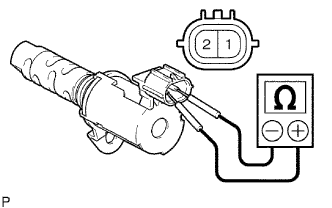
Measure the resistance according to the value(s) in the table below.
Standard Resistance Tester Connections Condition Specified Conditions 1 - 2 20°C (68°F) 6.9 to 7.9 Ω -
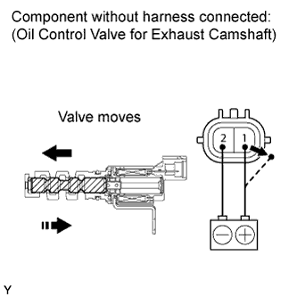
Apply the positive battery voltage to terminal 1 and negative battery voltage to terminal 2. Check the valve operation.
OK Valve moves quickly. -
Reinstall the camshaft timing oil control valve assembly.
NG
REPLACE CAMSHAFT TIMING OIL CONTROL VALVE ASSEMBLY (BANK 1 AND/OR BANK 2) Click here
OK
-
-
CHECK VALVE TIMING
-
Remove the cylinder head cover bank 1 and bank 2.
-
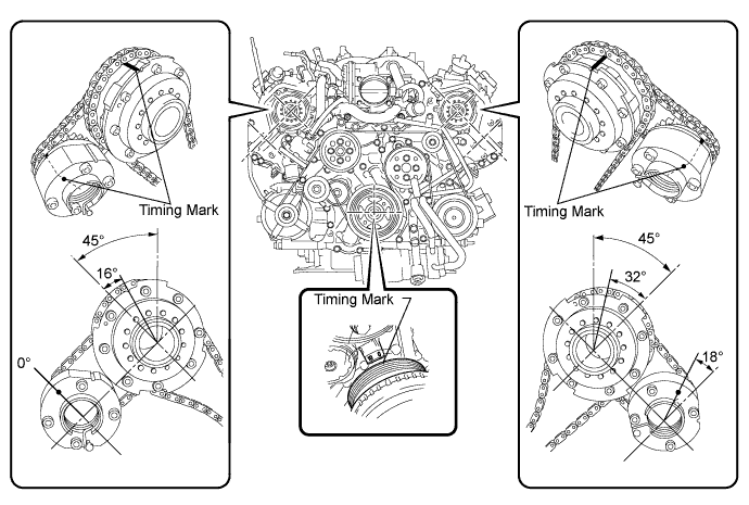
Turn the crankshaft pulley, and align its groove with the timing mark "0" of the timing chain cover.
-
Check that the timing marks of the camshaft timing gears and camshaft timing exhaust gears are at the positions shown in the illustration.
OK Timing marks on camshaft timing gears are aligned as shown in the illustration. -
Reinstall the cylinder head covers.
NG
ADJUST VALVE TIMING Click here
OK
-
-
REPLACE CAMSHAFT TIMING EXHAUST GEAR ASSEMBLY (BANK 1 AND/OR BANK 2)
-
Replace the camshaft timing exhaust gear assembly Click here.
NEXT
-
-
CONFIRM WHETHER MALFUNCTION HAS BEEN SUCCESSFULLY REPAIRED
-
To initialize the ECM's valve timing, disconnect the cable from the negative (-) battery terminal for 1 minute.
-
Connect the cable to the negative (-) battery terminal.
-
Connect the intelligent tester to the DLC3.
-
Switch the ECM from normal mode to check mode using the intelligent tester Click here.
-
Start the engine and idle it for 5 minutes.
-
Enter the following menus: Powertrain / Engine / DTC.
-
Read the DTCs.
Result Result Proceed to DTC is not output A Other DTCs are output B
B
GO TO DTC CHART Click here
A 
END
-