REPAIR INSTRUCTION INITIALIZATION
-
PROCEDURES NECESSARY WHEN BATTERY TERMINAL IS DISCONNECTED/RECONNECTED
Necessary Procedure Procedure Detail Effects/Inoperative Functions When Necessary Procedures are not Performed Note Correction of the steering angle neutral point Turn the steering wheel fully to the right, and left. Steering angle neutral point in memory Drive the vehicle at more than 20 km/h (12 mph) for more than 5 minutes on a straight road and with as little traffic congestion as possible. Note
It may not be possible to release the steering lock or start the engine when the battery voltage is low. If this occurs, initialization of the steering lock system is required. Click here
-
PROCEDURES NECESSARY WHEN ECU OR OTHER PARTS ARE REPLACED
Replacement Part Necessary Procedure Effect / Inoperative Function when Necessary Procedure is not Performed Note ECM
-
Reset memory (Automatic transmission system)
-
Perform road test to allow TCM to learn (Automatic transmission system)
-
Initialize distance control ECU (Dynamic radar cruise control system)
-
Large shift shock
-
The deterioration of fuel efficiency
-
Dynamic radar cruise control system
-
Pre-Crash safety System
- Code registration Engine start See the Service Bulletin for the registration method Engine assembly
-
Reset memory (Automatic transmission system)
-
Perform road test to allow TCM to learn (Automatic transmission system)
-
Large shift shock
-
The deterioration of fuel efficiency
- Distance control ECU Initialize distance control ECU (Dynamic radar cruise control system)
-
Dynamic radar cruise control system
-
Pre-Crash safety System
Do not turn the headlight dimmer switch on at this time because the optical axis automatic adjustment mode has already started Otherwise, the optical axis will be set incorrectly. If the headlight dimmer switch is turned on by mistake, readjust the optical axis. Millimeter wave radar sensor assembly Adjust millimeter wave radar sensor assembly (Dynamic radar cruise control system)
-
Dynamic radar cruise control system
-
Pre-Crash safety System
- Automatic transmission assembly
-
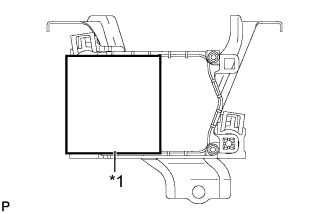
Set transmission compensation code (step 1) (Automatic transmission system) *1
-
Perform road test to allow TCM to learn (Automatic transmission system)
-
Large shift shock
-
The deterioration of fuel efficiency
-
-
Valve body assembly
-
Shift solenoid valve SL1, 2, 3, 4 and 5
Perform road test to allow TCM to learn (Automatic transmission system)
-
Large shift shock
-
The deterioration of fuel efficiency
- TCM (If possible, read the transmission compensation code from the previous TCM)
-
Transfer transmission compensation code (step 2) (Automatic transmission system) *2
-
Perform road test to allow TCM to learn (Automatic transmission system)
-
Large shift shock
-
The deterioration of fuel efficiency
- TCM (If impossible, read the transmission compensation code from the previous TCM)
-
Set transmission compensation code (step 1) (Automatic transmission system) *3
-
Perform road test to allow TCM to learn (Automatic transmission system)
-
Large shift shock
-
The deterioration of fuel efficiency
- Brake actuator assembly (Skid control ECU) Perform yaw rate and acceleration sensor zero point calibration and store system information (Vehicle Stability Control system)
-
Slip indicator light illumination
-
ABS warning light illumination
-
VSC disabled or malfunctioning
Perform yaw rate and acceleration sensor zero point calibration and store system information with the engine switch on (IG) (engine stopped). Yaw rate and acceleration sensor
-
Clearing zero point calibration data and system information (Vehicle Stability Control system)
-
Perform yaw rate and acceleration sensor zero point calibration and store system information (Vehicle Stability Control system)
-
Slip indicator light illumination
-
ABS warning light illumination
-
VSC disabled or malfunctioning
Perform yaw rate and acceleration sensor zero point calibration and store system information with the engine switch on (IG) (engine stopped).
-
Power steering ECU
-
Power steering gear assembly
Rotation angle sensor value initialization and torque sensor zero point calibration (Power steering system)
-
Steering wheel off-center
-
Difference in amount of steering assist between left and right
-
DTC output
-
EPS control
- Steering angle sensor
-
Correct the steering angle neutral point
-
Steering angle setting
Parking assist monitor system - Parking assist ECU Parking assist ECU initialization Parking assist monitor system - Rear television camera assembly Back camera position setting Parking assist monitor system Necessary when vehicle height changes due to replacement of the suspension or tire, etc.
-
Certification ECU (smart key ECU assembly)
-
ID code box (immobiliser code ECU)
-
Steering lock ECU
-
Key
Code registration
-
Wireless door lock control system
-
Entry and Start System
-
Engine start
See the Service Bulletin for the registration method Seat belt control ECU Initialization (Pre-Crash safety System) Pre-Crash safety System -
-
Power window regulator motor
-
Power window regulator
-
Door glass
-
Door glass run
Initialize power window control system (Power window regulator motor assembly (All doors))
-
AUTO UP / DOWN function
-
Power window operation function
-
Transmitter-linked function
-
Key-linked function
-
Jam protection function
-
-
Sliding roof drive gear (Sliding roof ECU)
-
Sliding roof housing
-
Sliding roof drive cable
Reset sliding roof drive gear sub-assembly (Sliding roof system)
-
AUTO operation
-
Sliding roof operation after engine switch is turned off
-
Jam protection function
-
Transmitter-linked operation function
-
Key-linked operation function (Driver's door only)
-
Entry lock switch-linked function
Necessary when removed and installed (Not necessary when the sliding roof drive gear (sliding roof ECU) is removed and installed together with the sliding roof housing). *1: New automatic transmission's compensation code.
*2: Read the compensation code from the previous TCM, then transfer it to the new TCM.
*3: Set the transmission compensation code of the current automatic transmission.
-
-
RESET MEMORY (Automatic transmission system)
Note
-
Perform Reset Memory (AT initialization) when replacing the engine assembly or ECM.
-
Reset Memory can be performed only with the intelligent tester.
-
Reset Memory cannot be completed by only disconnecting and reconnecting the cable to the negative (-) battery terminal.
Tech Tips
The TCM (ECT) memorizes the vehicle conditions when controlling the automatic transmission assembly and engine assembly.
-
The "Reset Memory" procedure is as follows:
-
Turn the engine switch off.
-
Connect the intelligent tester to the DLC3.
-
Turn the engine switch on (IG).
-
Turn the intelligent tester on.
-
Enter the following menus: Powertrain / ECT / Utility / Reset Memory.
Note
After performing the Reset Memory, be sure to perform the Road Test described previously Click here.
-
-
-
PERFORM ROAD TEST TO ALLOW TCM TO LEARN (Automatic transmission system)
CAUTION:
-
Perform the following procedures while strictly observing all traffic laws and speed limits.
-
Do not accelerate or decelerate rapidly.
-
"Road test" procedure is as follows:
-
Warm up the engine.
-
According to the replaced parts, perform the road test shown below.
Replaced Parts Road Test
-
Automatic transmission assembly
-
TCM
-
Valve body assembly
-
Shift solenoid valve SL3
-
Engine assembly
-
ECM
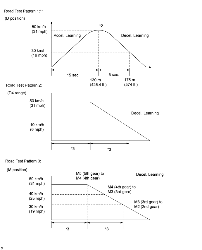
Perform pattern 1, 2 and 3
-
With shift lever in D, after gradually accelerating to 50 km/h (31 mph) or more, gradually decelerate to approx. 30 km/h (19 mph)
Pattern 1:*1
-
When driving at approximately 50 km/h (31 mph) with the D4 range selected, release the accelerator pedal to allow the vehicle to decelerate gradually to approximately 10 km/h (6 mph).
Pattern 2:
-
Accelerate to a speed higher than 50 km/h (31 mph). While gradually decelerating with shift lever in M and 5th gear selected, downshift to 4th gear at approx. 50 km/h (25 mph), to 3rd gear at approx. 40 km/h (25 mph), and to 2nd gear at approx. 30 km/h (19 mph).
Pattern 3:*2
-
Shift solenoid valve SL1
-
Shift solenoid valve SL2
-
Shift solenoid valve SL4
-
Shift solenoid valve SL5
Perform pattern 1 and 3
-
With shift lever in D, after gradually accelerating to 50 km/h (31 mph) or more, gradually decelerate to approx. 30 km/h (19 mph)
Pattern 1:*1
-
Accelerate to a speed higher than 50 km/h (31 mph). While gradually decelerating with shift lever in M and 5th gear selected, downshift to 4th gear at approx. 50 km/h (25 mph), to 3rd gear at approx. 40 km/h (25 mph), and to 2nd gear at approx. 30 km/h (19 mph).
Pattern 3:*2
Tech Tips
-
*1: After gradually accelerating for a distance of approximately 130 m (426.4 ft.) for a period of approximately 15 seconds, gradually decelerate for a distance of approximately 45 m (147.6 ft.) for a period of approximately 5 seconds.
-
*2: Accelerate the vehicle to a speed slightly higher than 50 km/h (31 mph).
Move the shift lever to M and select 5th gear.
Release the accelerator pedal and allow the vehicle to decelerate gradually.
When the vehicle decelerates to approximately 50 km/h (31 mph), downshift to 4th gear.
When the vehicle decelerates to approximately 40 km/h (25 mph), downshift to 3rd gear.
When the vehicle decelerates to approximately 30 km/h (19 mph), downshift to 2nd gear.
-
When decelerating, apply the brakes as necessary to adjust the vehicle speed.
Tech Tips
-
*1: The speed, time and distance values are approximate values.
-
*2: After accelerating, the deceleration does not need to be performed immediately.
-
*3: There is no specified time or distance.
-
-
Repeat the road tests until the shift shock and engine speed overrun (engine speed flare when shifting) reach an acceptable level.
Note
When repeating the acceleration/deceleration cycle of a road test pattern, bring the vehicle to a complete stop before accelerating again.
-
-
-
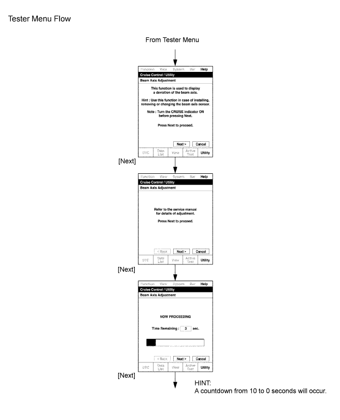
INITIALIZE DISTANCE CONTROL ECU (Dynamic radar cruise control system)
Note
When replacing the distance control ECU, perform the following procedure so that the ECU can the specification
-
Be sure to perform the following procedure after replacing the distance control ECU.
-
Turn the engine switch on (IG).
-
Turn the cruise control main switch on.
-
With the brake pedal depressed, push the cruise control main switch to RES/ACC 3 times within 3 seconds. Check that the buzzer sounds at this time.
-
-
Perform any of the following to cancel beam axis adjustment mode.
-
Turn the cruise control main switch off.
-
Turn the engine switch off.
-
Accelerate the vehicle to 10 km/h or more.
-
-
-
ADJUST MILLIMETER WAVE RADAR SENSOR ASSEMBLY (Dynamic radar cruise control system)
Text in Illustration *1 Approx. 10 m *2 Approx. 14 m CAUTION:
Exposure to radio frequency emissions is hazardous to your health. It is hazardous to your health to be within 20 cm (7.87 in.) of the device's radio frequency aperture.
Note
-
This device complies with FCC radio frequency emission regulations.
-
Perform measurements on a level surface.
-
Make sure that no large pieces of metal are within a 10 m (32.81 ft.) x 14 m (45.93 ft.) area in front of the vehicle. If possible, the surrounding area should also be free of large metal objects.
-
Before adjusting the radar beam axis, prepare the vehicle as follows:
-
Check the tire pressure and adjust it if necessary.
-
Remove all excess weight from the vehicle (luggage, heavy objects, etc.).
-
-
Check and adjust the vertical direction of the radar sensor.
-
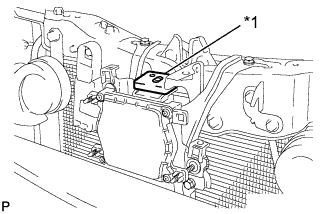
Text in Illustration *1 Level Remove dust, oil, and foreign matter from the radar sensor's level rack.
-
Set a level on the radar sensor's level rack.
-
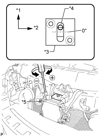
Text in Illustration *1 FR *2 RH *3 Level *4 Air Bubble *5 Bolt A Check that the air bubble is within the red frame on the level.
Tech Tips
-
The adjustable range within the red frame on the level is +/- 0.2°.
-
The target angle is +0.2° (upward angle of 0.2°).
-
-
-
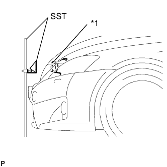
Text in Illustration *1 Millimeter Wave Radar Sensor Adjust the reflector height.
-
Adjust the reflector so that the center of the SST reflector is the same height as the millimeter wave radar sensor.
- SST
- 09870-60000 ( 09870-60010 )
- 09870-60040
Tech Tips
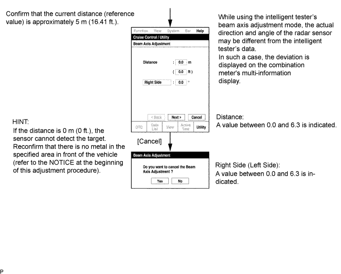
Prepare a 10 m (32.81 ft.) string, a string with a sharp-pointed weight (plumb bob), and a 5 m (16.41 ft.) tape measure.
-
-
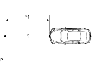
Place the reflector.
Text in Illustration *1 Approx. 5 m
-
Hang the string (with a weight) from the center of the vehicle rear emblem. Mark the vehicle rear center point on the ground. Repeat the same procedure for the front of the vehicle.
-
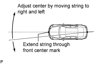
Set one end of the 10 m (32.82 ft.) string on the vehicle rear center point. Run the string over the vehicle front center point to a position 5 m (16.41 ft.) beyond the vehicle front center point, as shown in the illustration. Mark the 5 m (16.41 ft.) position.
-
Using the tape measure, measure 9.9 mm (0.389 in.) to the right of the 5 m (16.41 ft.) position. Place the reflector at that position.
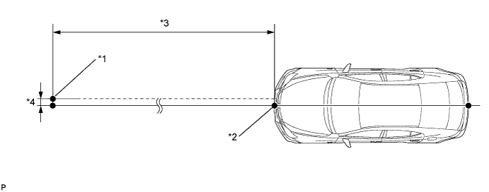
Text in Illustration *1 Reflector Placement Point *2 Millimeter Wave Radar Sensor Position *3 Approx. 5 m *4 Approx. 9.9 mm Note
Perform the operation as precisely as possible.
-
-
Adjust the radar beam axis.
-
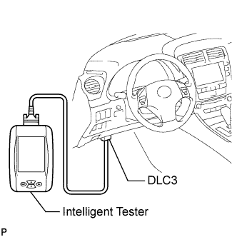
Connect the intelligent tester to the DLC3.
-
Turn the engine switch on (IG).
-
Turn the intelligent tester main switch on, and turn the cruise control main switch on.
Tech Tips
If an error message is displayed on the screen, initialization of the distance control ECU may not be completed. Initialize the distance control ECU Click here.
-
-
Check and adjust the horizontal direction of the radar sensor.
-
Check that the divergence of the radar beam axis is 0° .
-
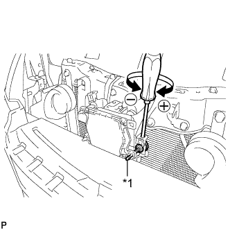
Text in Illustration *1 Bolt B Based on the measured divergence of the beam axis, turn and adjust bolt B for horizontal adjustment of the millimeter wave radar sensor using a screwdriver.
Tech Tips
-
If "LEFT SIDE: 1.0°" is displayed, the divergence is 1.0° to the left . Turn bolt B approximately 3 turns to the negative (-) side.
-
If the value does not change to 0°, it is possible that the sensor is aiming at something different. Reconfirm that there are no reflective materials in the surrounding area.
-
-
Text in Illustration *1 Metal (such as aluminum foil) Reset the radar sensor's driving learning values. Prepare a piece of metal that can block radio waves, such as aluminum foil. Cover the radar sensor's right half with the aluminum foil for 10 seconds.
Note
Be sure to keep the reflector in place and make sure that there is nothing between the sensor's left half and the reflector.
Tech Tips
When the reset is completed, the buzzer sounds for 10 seconds.
-
Disconnect the intelligent tester from the DLC3.
-
-
Recheck and readjust the vertical direction of the radar sensor.
-
Text in Illustration *1 Level Set a level on the radar sensor's level rack.
-
Text in Illustration *1 FR *2 RH *3 Level *4 Air Bubble *5 Bolt A Check that the air bubble is within the red frame on the level.
Tech Tips
-
The adjustable range within the red frame on the level is +/- 0.2°.
-
The target angle is +0.2° (upward angle of 0.2°).
-
-
-
-
SET TRANSMISSION COMPENSATION CODE INTO TCM (step 1) (Automatic transmission system)
Note
Transmission compensation codes are unique, 60-digit alphanumeric values printed on a QR label on the transmission. If an incorrect transmission compensation code is input into the TCM, shift shock may occur.
-
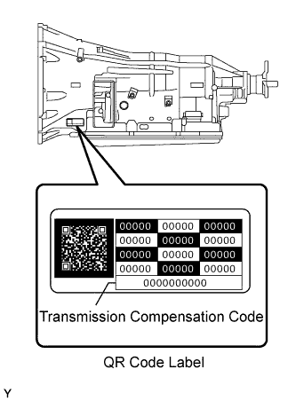
Record the transmission compensation code specified on the QR label.
Tech Tips
The transmission compensation code is a 60-digit alphanumeric value imprinted on the QR label.
-
Move the shift lever to N or P.
-
Connect the intelligent tester to the DLC3.
-
Turn the engine switch on (IG).
Note
Do not start the engine.
-
Turn the intelligent tester on.
-
Enter the following menus: Powertrain / ECT / Utility / A/T Code Registration.
-
Select "Set Compensation Code".
-
Register the compensation code.
-
Manually input the transmission compensation code.
-
Check that the compensation code displayed on the screen is correct by comparing it with the 60-digit alphanumeric value on the QR label.
Note
If an incorrect transmission compensation code is input into the TCM, shift shock will occur.
Tech Tips
Input letters and numbers using the intelligent tester.
-
Set the compensation code to the TCM.
-
-
TRANSFER TRANSMISSION COMPENSATION CODE (step 2) (Automatic transmission system)
Note
Transmission compensation codes are unique, 60-digit alphanumeric values printed on a QR label on the transmission. If an incorrect transmission compensation code is input into the TCM, shift shock may occur.
Tech Tips
The following operation is available for use when a TCM that is being replaced can still transmit its registered transmission compensation code to the intelligent tester.
-
Read the transmission compensation code.
-
Move the shift lever to N or P.
-
Connect the intelligent tester to the DLC3.
-
Turn the engine switch on (IG).
Note
Do not start the engine.
-
Turn the intelligent tester on.
-
Enter the following menus: Powertrain / ECT / Utility / A/T Code Registration.
-
Select "Read Compensation Code".
Note
Do not use the code specified on the transmission QR label even if the transmission compensation code cannot be read using the intelligent tester. The code printed on an in-service transmission may not match its current characteristics. Replace the TCM with a new one and perform a road test to allow the TCM to learn the transmission characteristics.
-
Turn the engine switch off.
-
Replace the TCM.
-
-
Set the transmission compensation code.
-
Turn the engine switch on (IG).
Note
Do not start the engine.
-
Turn the intelligent tester on.
-
Enter the following menus: Powertrain / ECT / Utility / A/T Code Registration.
-
Select "Set Compensation Code".
-
Press "Open".
-
Select "Open".
-
Set the compensation code to the TCM.
-
-
-
PERFORM YAW RATE AND ACCELERATION SENSOR ZERO POINT CALIBRATION AND STORE SYSTEM INFORMATION (Vehicle Stability Control system)
Note
-
Stored system information cannot be overwritten unless it is cleared. Clear the stored information and then store new system information.
-
While obtaining the zero point, keep the vehicle stationary and do not vibrate, tilt, move, or shake it. (Do not start the engine.)
-
Be sure to perform this procedure on a level surface (with an inclination of less than 1 degree).
-
Clear the zero point calibration data and system information.
Note
Performing the following procedure will clear the zero point of the yaw rate and acceleration sensor and system information simultaneously.
-
Turn the engine switch off.
-
Check that the steering wheel is centered.
-
Check that the shift lever is in P.
-
Connect the intelligent tester to the DLC3.
-
Turn the engine switch on (IG).
-
Turn the intelligent tester on.
-
Select the skid control ECU to clear the zero point calibration data using the intelligent tester. Enter the following menus: Chassis / ABS/VSC/TRC / Utility / Reset Memory.
-
Turn the engine switch off.
Note
-
If the vehicle is driven after the zero point of the yaw rate and acceleration sensor and system information are cleared, DTCs will be stored.
-
If the engine switch is turned on (IG) for more than 15 seconds with the shift lever in P after the zero point of the yaw rate and acceleration sensor have been cleared, only the zero point of the yaw rate sensor will be stored. If the vehicle is driven under these conditions, the skid control ECU will store the zero point calibration for the acceleration sensor as not being completed. The skid control ECU will then also indicate this as a malfunction of the VSC system using the indicator lights.
-
-
-
Perform the yaw rate and acceleration sensor zero point calibration and store system information.
Note
Performing the following procedure will perform the yaw rate and acceleration sensor zero point calibration and store system information simultaneously.
-
Turn the engine switch off.
-
Check that the steering wheel is centered.
-
Check that the shift lever is in P.
Note
-
DTCs C1210 (Zero Point Calibration of Yaw Rate Sensor Undone) and C1336 (Zero Point Calibration of Acceleration Sensor Undone) will be recorded if the shift lever is not in P.
-
If a DTC is stored that indicates zero point calibration is incomplete, repeat the procedure starting at the step for clearing the zero point calibration data and system information.
-
-
Connect the intelligent tester to the DLC3.
-
Turn the engine switch on (IG).
-
Turn the intelligent tester on.
-
Switch the skid control ECU to Test Mode using the intelligent tester. Enter the following menus: Chassis / ABS/VSC/TRC / Utility / Test Mode.
-
After Test Mode has been entered, keep the vehicle stationary on a level surface for 2 seconds or more.
-
Check that the ABS warning and slip indicator lights come on for several seconds and then blink in Test Mode.
Tech Tips
-
If the ABS warning and slip indicator lights do not blink, perform zero point calibration again.
-
The zero point calibration is performed only once after the system enters Test Mode.
-
Calibration cannot be performed again until the stored data is cleared.
-
-
Turn the engine switch off and disconnect the intelligent tester.
-
-
-
CLEAR THE ZERO POINT CALIBRATION DATA AND SYSTEM INFORMATION (Vehicle Stability Control system)
-
Clear the zero point calibration data and system information.
Note
Performing the following procedure will clear the zero point of the yaw rate and acceleration sensor and system information simultaneously.
-
Turn the engine switch off.
-
Check that the steering wheel is centered.
-
Check that the shift lever is in P.
-
Connect the intelligent tester to the DLC3.
-
Turn the engine switch on (IG).
-
Turn the intelligent tester on.
-
Select the skid control ECU to clear the zero point calibration data using the intelligent tester. Enter the following menus: Chassis / ABS/VSC/TRC / Utility / Reset Memory.
-
Turn the engine switch off.
Note
-
If the vehicle is driven after the zero point of the yaw rate and acceleration sensor and system information are cleared, DTCs will be stored.
-
If the engine switch is turned on (IG) for more than 15 seconds with the shift lever in P after the zero point of the yaw rate and acceleration sensor have been cleared, only the zero point of the yaw rate sensor will be stored. If the vehicle is driven under these conditions, the skid control ECU will store the zero point calibration for the acceleration sensor as not being completed. The skid control ECU will then also indicate this as a malfunction of the VSC system using the indicator lights.
-
-
-
-
ROTATION ANGLE SENSOR VALUE INITIALIZATION AND TORQUE SENSOR ZERO POINT CALIBRATION (Power steering system)
Note
Clear the rotation angle sensor calibration value, initialize the rotation angle sensor value, and calibrate the torque sensor zero point if any of the following has occurred:
-
The power steering ECU assembly has been replaced.
-
The power steering gear assembly has been replaced.
-
Steering effort differs between left and right.
-
Inspection before calibration
-
Turn the engine switch off.
-
Connect the intelligent tester to the DLC3.
-
Turn the engine switch on (IG).
-
Turn the intelligent tester on.
-
Check the IG power supply voltage on the intelligent tester. Enter the following menus: Chassis / EMPS / Data List.
EMPS Tester Display Measurement Item/Range Normal Condition Diagnostic Note IG Power Supply ECU power source voltage/
Min.: 0 V
Max.: 20.1531 V
11 to 14 V Engine switch on (IG) Note
If the IG power supply voltage is less than 11 V, calibration cannot be performed. In this case, charge or replace the battery, and then perform calibration.
-
-
Rotation angle sensor calibration value clear, rotation angle sensor value initialization, and torque sensor zero point calibration.
Note
-
If DTC C1516 (Torque Sensor Zero Point Adjustment Incomplete) is stored, the torque sensor zero point cannot be calibrated. Clear the DTC before starting calibration.
-
If DTC C1526 (Rotation Angle Sensor Initialization Incomplete) is stored, the rotation angle sensor value cannot be initialized. Clear the DTC before starting initialization.
-
Turn the engine switch off.
-
Connect the intelligent tester to the DLC3.
-
Turn the engine switch on (IG).
-
Turn the intelligent tester on.
-
Follow the procedures on the intelligent tester to clear the rotation angle sensor calibration value, initialize the rotation angle sensor value, and calibrate the torque sensor zero point. Enter the following menus: Chassis / EMPS / Utility / Torque Sensor Adjustment.
Note
-
When initializing the rotation angle sensor value, observe the following to stabilize sensor voltage:
After turning the engine switch on (IG), wait for at least 2.5 seconds before turning the steering wheel. Do not turn the steering wheel quickly.
-
The steering wheel will vibrate during torque sensor zero point calibration. Do not touch the steering wheel while it is vibrating or for 2 seconds after it stops.
-
-
-
-
CORRECT THE STEERING ANGLE NEUTRAL POINT (Parking Assist Monitor System)
-
When "System initializing" message is displayed on the navigation display, correct the steering angle neutral point using the following method.
-
Fully turn the steering wheel to the right and left on the flat ground.
Note
Memorizing the steering angle neutral point must be carried out with the engine started. Apply the parking brake, depress the brake pedal, check that the shift lever is in P, and ensure that the vehicle is not moving.
Tech Tips
The "?" button is displayed at the same time as "System initializing" message. If the "?" button is selected, this method is displayed.
-
-
-
STEERING ANGLE SETTING (Parking Assist Monitor System)
-
STEERING ANGLE SETTING
-
Perform the STEERING CENTER MEMORIZE operation.
-
Check that the steering wheel is centered, and then select "STEERING CENTER MEMORIZE".
Tech Tips
When performing removal and installation, or replacement of the rear television camera, steering angle adjustment is not required.
-
-
Perform the MAX STEERING ANGLE MEMORIZE operation.
-
After adjusting the steering angle neutral point, turn the steering wheel to the left and right lock positions and select "MAX STEERING ANGLE MEMORIZE". The maximum steering angle is then stored and the screen changes to the BACK CAMERA POSITION SETTING screen.
Tech Tips
The "NEXT" button does not respond until the system stores the steering angle neutral point and maximum steering angle.
Tech Tips
-
It is also possible to start by initially turning the steering to the right side.
-
When "MAX STEERING ANGLE MEMORIZE" is selected, a beep will sound to confirm that the steering adjustment values have been stored.
-
The adjustment value will not be stored unless "MAX STEERING ANGLE MEMORIZE" is selected after turning the steering wheel side to side.
-
When "BACK" is selected, the screen changes to SIGNAL CHECK screen without storing the set values.
-
Even if no DTCs are detected, selecting "MAX STEERING ANGLE MEMORIZE" may not cause the adjustment value to be stored if the steering angle sensor is malfunctioning.
-
If selecting "MAX STEERING ANGLE MEMORIZE" does not cause the adjustment value to be stored after adjusting the steering angle, replace the steering angle sensor.
-
-
-
-
-
PARKING ASSIST ECU INITIALIZATION (Parking Assist Monitor System)
Tech Tips
Be sure to check for DTCs before performing this procedure.
-
Preparation for adjustment
-
Park the vehicle with the steering wheel centered.
-
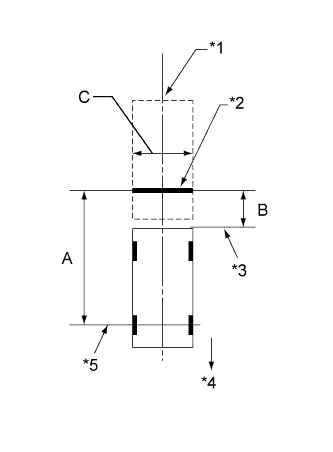
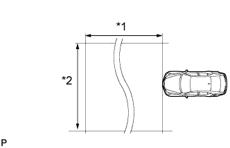
Text in Illustration *1 Vehicle Center *2 Target Bar for Back Camera Position Setting *3 Vehicle End *4 Front Side *5 Front Wheel Axis Set a target bar behind the vehicle for optical axis adjustment of the rear television camera assembly.
Tech Tips
Only when adjusting the optical axis of the camera, create a target bar for adjustment.
Tech Tips
-
Set a piece of tape on the ground as the target bar for adjustment. Its width and length should be 20 to 30 mm (0.787 to 1.181 in.) and 1995 to 2005 mm (6.545 to 6.578 ft.), respectively. Check the color on the navigation display and choose a tape color which can be easily seen.
-
Before parking the vehicle, be sure to move the vehicle forward and in reverse to check that the tires are facing straight ahead with the steering wheel centered.
-
Check that the luggage compartment door is fully closed.
-
-
-
Start diagnostic mode.
Note
Parking assist ECU initialization must be entered with the engine started. Apply the parking brake, depress the brake pedal, check that the shift lever is in P, and ensure that the vehicle is not moving.
-
Select "Function Check/Setting" on the Service Menu screen.
-
Select "Camera Setting" on the Function Check/Setting screen.
-
-
STEERING ANGLE SETTING
-
Perform the STEERING CENTER MEMORIZE operation.
-
Check that the steering wheel is centered, and then select "STEERING CENTER MEMORIZE".
Tech Tips
When performing removal and installation, or replacement of the rear television camera, steering angle setting is not required.
-
-
Perform the MAX STEERING ANGLE MEMORIZE operation.
-
After performing the steering center memorize operation, turn the steering wheel to the left and right lock positions and select "MAX STEERING ANGLE MEMORIZE". The maximum steering angle is then stored and the screen changes to the BACK CAMERA POSITION SETTING screen.
Tech Tips
The "NEXT" button does not respond until the system memorizes the steering center and maximum steering angle.
Tech Tips
-
It is also possible to start by initially turning the steering to the right side.
-
When "MAX STEERING ANGLE MEMORIZE" is selected, a beep will sound to confirm that the adjustment values have been stored.
-
The adjustment value will not be stored unless "MAX STEERING ANGLE MEMORIZE" is selected after turning the steering wheel from lock to lock.
-
When "BACK" is selected, the screen changes to SIGNAL CHECK screen without storing any values.
-
Even if no DTCs are detected, selecting "MAX STEERING ANGLE MEMORIZE" may not cause the adjustment value to be stored if the steering angle sensor is malfunctioning.
-
If selecting "MAX STEERING ANGLE MEMORIZE" does not cause the adjustment value to be stored after performing the steering angle setting procedure, replace the steering angle sensor.
-
-
-
-
BACK CAMERA POSITION SETTING
Tech Tips
-
When the luggage compartment door is open, a luggage compartment door open warning message will be displayed and camera position setting will not be possible.
-
If a luggage compartment door open warning message is displayed even when the luggage compartment door is closed, perform inspections according to the following inspection procedure: "A luggage compartment door open warning message is displayed even after luggage compartment door is closed".
-
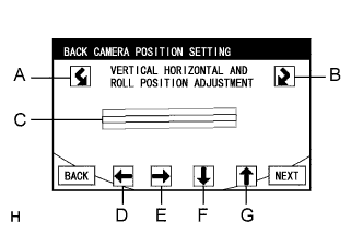
Perform roll angle adjustment.
-
Select switches A and B to rotate C so that it is parallel to the target bar for back camera adjustment.
-
-
Perform vertical and horizontal position adjustment.
-
Use directional switches D, E, F and G to move C so that the target bar for back camera adjustment is centered in C.
-
-
Select the "NEXT" button on the BACK CAMERA POSITION SETTING screen.
-
-
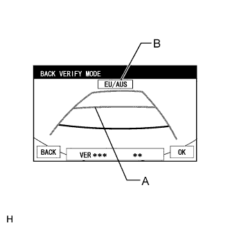
BACK VERIFY MODE
-
Check that A and the target bar for back camera adjustment are overlapping.
-
Check that vehicle width extension line and predicted path line are overlapping.
-
If the lines are not aligned, perform the STEERING CENTER MEMORIZE and MAX STEERING ANGLE MEMORIZE operations.
-
If A and the target bar for back camera adjustment are not aligned even if the tires are aligned straight ahead, perform the back camera position setting operation.
-
-
Check that B (destination information) is correct by referring to the table below.
B Destination EU/AUS Europe, Australia, New Zealand TAIWAN Taiwan Tech Tips
If "CHK" (red) is displayed, check for DTCs and perform troubleshooting based on the output DTCs.
-
Selecting "OK" will return the screen to the Service Menu screen, and complete the adjustment.
Tech Tips
-
The update is not completed until "OK" is selected.
-
When "OK" is selected, a beep will sound to confirm that the adjustment values have been stored.
-
The adjustment values are not stored until the beep has sounded.
-
-
-
Finish diagnostic mode.
-
-
BACK CAMERA POSITION SETTING (Parking Assist Monitor System)
Tech Tips
Be sure to check for DTCs before performing this procedure.
-
Preparation for adjustment
-
Park the vehicle with the steering wheel centered.
-
Text in Illustration *1 Vehicle Center *2 Target Bar for Back Camera Position Setting *3 Vehicle End *4 Front Side *5 Front Wheel Axis Set a target bar behind the vehicle for optical axis adjustment of the rear television camera.
Tech Tips
Only when adjusting the optical axis of the camera, create a target bar for adjustment.
Tech Tips
-
Set a piece of tape on the ground as the target bar for adjustment. Its width and length should be 20 to 30 mm (0.787 to 1.181 in.) and 1995 to 2005 mm (6.545 to 6.578 ft.), respectively. Check the color on the navigation display and choose a tape color which can be easily seen.
-
Before parking the vehicle, be sure to move the vehicle forward and in reverse to check that the tires are facing straight ahead with the steering wheel centered.
-
Check that the luggage compartment door is fully closed.
-
-
-
Start diagnostic mode.
Note
Back camera position setting must be performed with the engine started. Apply the parking brake, depress the brake pedal, check that the shift lever is in P, and ensure that the vehicle is not moving.
-
Select "Function Check/Setting" on the Service Menu screen.
-
Select "Camera Setting" on the Function Check/Setting screen.
-
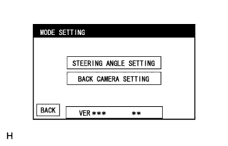
Select "BACK CAMERA SETTING" on the MODE SETTING screen.
Tech Tips
To select a grayed out item, select and hold the item for 2 seconds or more.
-
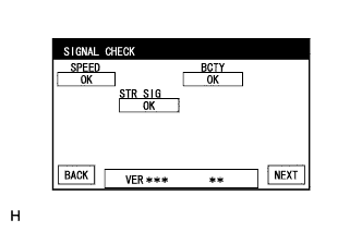
Select "NEXT" on the SIGNAL CHECK screen.
Note
-
When "CHK" (red) is displayed for any items on the SIGNAL CHECK screen, selecting "NEXT" will not change the screen to the BACK CAMERA POSITION SETTING screen.
-
When "CHK" (red) is displayed for any items on the SIGNAL CHECK screen, perform inspections using the SIGNAL CHECK screen.
-
-
-
BACK CAMERA POSITION SETTING
Tech Tips
-
When the luggage compartment door is open, a luggage compartment door open warning message will be displayed and camera position setting will not be possible.
-
If a luggage compartment door open warning message is displayed even when the luggage compartment door is closed, perform inspections according to the following inspection procedure: "A luggage compartment door open warning message is displayed even after luggage compartment door is closed".
-
Perform roll angle adjustment.
-
Select switches A and B to rotate C so that it is parallel to the target bar for back camera adjustment.
-
-
Perform vertical and horizontal position adjustment.
-
Use directional switches D, E, F and G to move C so that the target bar for back camera adjustment is centered in C.
-
-
Select the "NEXT" button on the "BACK CAMERA POSITION SETTING" screen.
-
-
BACK VERIFY MODE
-
Check that A and the target bar for back camera adjustment are overlapping.
-
Check that vehicle width extension line and predicted path line are overlapping.
-
If the lines are not aligned, perform the STEERING CENTER MEMORIZE and MAX STEERING ANGLE MEMORIZE operations.
-
If A and the target bar for back camera adjustment are not aligned even if the tires are aligned straight ahead, perform the back camera position setting operation.
-
-
Check that B (destination information) is correct by referring to the table below.
B Destination EU/AUS Europe, Australia, New Zealand TAIWAN Taiwan Tech Tips
If "CHK" (red) is displayed, check for DTCs and perform troubleshooting based on the output DTCs.
-
Selecting "OK" will return the screen to the Service Menu, and complete the adjustment.
Tech Tips
-
The update is not completed until "OK" is selected.
-
When "OK" is selected, a beep will sound to confirm that the back camera aiming adjustment values have been stored.
-
The adjustment values are not stored until the beep has sounded.
-
-
-
Finish diagnostic mode.
-
-
INITIALIZATION (Pre-crash safety system) (Precautions for Seat Belt Control ECU Replacement)
The seat belt control ECU operates the pre-crash safety system based on the stored data that informs that the vehicle is LHD or RHD model. LHD or RHD refers to the seating position of the driver, not which side of the road the vehicle is driven on.
Therefore, when replacing the seat belt control ECU, it is necessary to store the information about whether the vehicle is a LHD or RHD model. This can be performed by following these steps:
-
Turn the engine switch on (IG).
-
The PCS warning light comes on for at least 3 seconds after turning the engine switch on (IG). Make sure that the warning light does not remain on.
-
At this time, the seat belt control ECU receives vehicle configuration (LHD/RHD) information from the gateway ECU and stores it in memory.
-
Connect the intelligent tester to the DLC3.
-
Turn the engine switch on (IG).
-
Turn the tester on.
-
Enter the following menus: Body / Pre-Crash / Active Test.
-
Perform Active Test according to the display on the tester.
Pre-Crash Tester Display Test Part Control Range Diagnostic Note Driver Seat Belt Motor Driver's seat belt motor ON: Seat belt motor operate
OFF: Seat belt motor does not operate
Seat belt (driver side) is fastened Passenger Seat Belt Motor Passenger's seat belt motor ON: Seat belt motor operate
OFF: Seat belt motor does not operate
Seat belt (passenger side) is fastened
-
-
-
INITIALIZE POWER WINDOW CONTROL SYSTEM (POWER WINDOW REGULATOR MOTOR ASSEMBLY (ALL DOORS)) (Power window control system)
CAUTION:
When the power window regulator motor assembly is reinstalled or replaced, the power window control system must be initialized. Functions such as the auto up/down, jam protection, remote control and key-off operation do not operate if the initialization is not performed.
Tech Tips
When the battery is replaced, it is not necessary to initialize the power window regulator motor assembly.
Note
-
When the power window regulator motor assembly is replaced, DTC B2313 is output. Clear the DTC after the initialization.
-
When performing initialization, do not perform any other procedures.
-
After a door glass or a door glass run has been replaced, the jam protection function may operate unexpectedly when the auto up function is used, due to detection of a value different from the operation learned value of the door glass movement speed. In such cases, the auto up function can be reinitialized by repeating the following operation at least 5 times:
-
Open the power window by fully pushing down the multiplex network master switch assembly or power window regulator switch assembly.
-
Close the power window by fully pulling up the multiplex network master switch assembly or power window regulator switch assembly and holding it at the auto up position.
-
If the initialization is not completed properly, the LIN communication line may have a malfunction.
-
Initialization procedures when replacing the power window regulator motor assembly with a new one:
-
Connect the battery and turn the engine switch on (IG) (at this time, the LED on the multiplex network master switch assembly or power window regulator switch assembly blinks to indicate that it is ready for initialization).
-
Fully open the window by fully pushing down the multiplex network master switch assembly or power window regulator switch assembly, and hold the switch for 1 second or more after the window is fully opened.
-
Fully close the power window by fully pulling up the multiplex network master switch assembly or power window regulator switch assembly, and hold the switch for 1 second or more after the window is fully closed to reset the glass position. The LED on the multiplex network master switch assembly or power window regulator switch assembly stops blinking and illuminates to indicate that the initialization is complete.
-
-
Initialization procedures when removing/installing the power window regulator motor assembly:
-
Connect the battery and turn the engine switch on (IG).
-
Fully close the power window by fully pulling up the multiplex network master switch assembly or power window regulator switch assembly, and hold the switch for 6 seconds or more after the window is fully closed (if the power window does not move or stops halfway even when the switch is fully pulled, release the switch and fully pull it again).
-
Fully open the window by pushing down the multiplex network master switch assembly or power window regulator switch assembly, and hold the switch for 1 second or more after the window is fully opened.
-
Release the multiplex network master switch assembly or power window regulator switch assembly. Then fully push down and hold the switch for 4 seconds or more.
-
Fully close the power window by fully pulling up the multiplex network master switch assembly or power window regulator switch assembly, and hold the switch for 1 second or more after the window is fully closed to reset the glass position and complete the initialization.
-
-
Initialization procedures when the power window does not fully open:
-
Connect the battery and turn the engine switch on (IG).
-
Fully close the power window by fully pulling up the multiplex network master switch assembly or power window regulator switch assembly, and hold the switch for 6 seconds or more after the window is fully closed (if the power window does not move or stops halfway even when the switch is fully pulled, release the switch and fully pull it again).
-
Fully open the window by pushing down the multiplex network master switch assembly or power window regulator switch assembly, and hold the switch for 1 second or more after the window is fully opened.
-
Release the multiplex network master switch assembly or power window regulator switch assembly. Then fully push down and hold the switch for 4 seconds or more.
-
Fully close the power window by fully pulling up the multiplex network master switch assembly or power window regulator switch assembly, and hold the switch for 1 second or more after the window is fully closed to reset the glass position and complete the initialization.
-
-
-
INITIALIZE SLIDING ROOF DRIVE GEAR SUB-ASSEMBLY (Sliding roof system)
Note
-
Before starting this operation, make sure that the guide rails are not deformed and there is no foreign object on the guide rails.
-
When the sliding roof glass is adjusted or removed/installed, or the sliding roof drive gear assembly is replaced, the sliding roof ECU (sliding roof drive gear) must be initialized (pulse sensor initial position setting). Failure to initialize could result in displacement of the roof glass set position, defects in the automatic systems or the roof glass moving in the reverse direction.
-
During initialization, do not apply a physical shock, such as opening/closing a door or driving the vehicle at 5 km/h (3 mph) or more, to the vehicle and do not perform the following electrical operations:
-
Cranking the engine
-
Turning the engine switch from on (IG) to off
-
Operating the power window switches
-
Operating the window defogger switch
-
Operating the blower switch
-
Locking/Unlocking a door
-
Operating the headlight dimmer switch
-
Operating the power seat switch
Tech Tips
The sliding roof switch assembly is attached to the map light assembly.
-
Initialization
Tech Tips
Perform initialization according to the table below.
Condition of Sliding Roof Proceed to Auto slide open and close/tilt up and down function does not operate. Procedure A Automatically moves, but the sliding roof glass does not stop at the right position (displacement occurs). Or, the sliding roof glass moves in the reverse direction during tilt down operation. Procedure B Automatically moves, but the sliding roof glass moves in the reverse direction during slide close operation. Procedure C
-
Procedure A
-
Turn the engine switch on (IG).
-
Fully close the sliding roof glass and release the sliding roof switch.
-
Press and hold the UP switch.
-
Sliding roof glass moves in the following order: tilt up → 1 second pause → tilt down → slide open → slide closed
-
After stopping the sliding roof glass in the fully closed position, release the switch.
Note
Press and hold the UP switch until step 5 is completed. If the switch is released before step 5 is completed, repeat the operation starting at step 2.
-
Make sure that the sliding roof works automatically in the normal manner.
-
-
Procedure B
-
Turn the engine switch on (IG).
-
Press the UP switch to move the sliding roof glass into the fully tilted up position and then release the UP switch.
Tech Tips
-
If the sliding roof glass cannot be fully tilted up due to misalignment of the roof glass, press and hold the CLOSE switch until the sliding roof glass stops closing, and then press and hold the UP switch until the sliding roof glass stops tilting up.
-
If the sliding roof glass moves in the reverse direction while it is being closed, repeatedly tap the CLOSE switch at short intervals to fully close the sliding roof glass. When the sliding roof glass is fully closed, press the UP switch to move the sliding roof glass into the fully tilted up position.
-
-
Press and hold the UP switch again for 10 seconds to move the sliding roof glass in the following order: tilt inching motion → 1 second pause → tilt down → slide open → slide closed
-
After stopping the sliding roof glass in the fully closed position, release the switch.
Note
-
Press and hold the UP switch until step 4 is completed.
-
While performing step 3, if the UP switch is released before it is pressed for 10 seconds, start this step over.
-
While performing step 3, if the UP switch is released after it is pressed for 10 seconds or longer, the automatic system will not work. In such a case, perform procedure [A] to complete initialization.
-
-
Make sure that the sliding roof works automatically in the normal manner.
-
-
Procedure C
-
Turn the engine switch on (IG).
-
Press and hold the CLOSE switch to move the sliding roof glass in the following order: slide closed → move in the reverse direction → pause → start closing after approximately 10 seconds → tilt up → 1 second pause → tilt down → slide open → slide closed
-
After stopping the sliding roof glass in the fully closed position, release the switch.
Note
-
Press and hold the CLOSE switch until step 3 is completed.
-
While performing step 2, if the CLOSE switch is released before it is pressed for 10 seconds, start this step over.
-
While performing step 2, if the CLOSE switch is released after it is pressed for 10 seconds or longer, the automatic system will not work. In such a case, perform procedure [A] to complete initialization.
-
-
Make sure that the sliding roof works automatically in the normal manner.
-
-
Note
-
If the battery voltage changes during initialization, the sliding roof ECU may not be initialized normally.
-
Do not apply excessive loads to the vehicle during initialization by performing operations such as locking the doors or cranking the engine.
-
Do not turn the engine switch off during initialization.
-
Do not move the vehicle during initialization.
-
Do not apply strong impacts to the vehicle during initialization by performing operations such as closing the doors forcefully.
-