REPAIR INSTRUCTION PRECAUTION
-
BASIC REPAIR HINT
-
HINTS ON OPERATIONS
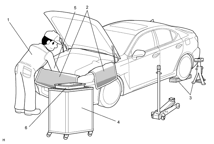
1 Attire
-
Always wear a clean uniform.
-
A hat and safety shoes must be worn.
2 Vehicle protection Prepare a grille cover, fender cover, seat cover and floor mat before starting an operation. 3 Safety procedure
-
When working with 2 or more persons, be sure to check the safety of one another.
-
When working with the engine running, make sure to provide ventilation for exhaust fumes in the workshop.
-
If working on high temperature, high pressure, rotating, moving, or vibrating parts, wear appropriate safety equipment and take extra care not to injure yourself or others.
-
When jacking up the vehicle, be sure to support the specified location with a safety stand.
-
When lifting up the vehicle, use appropriate safety equipment.
4 Preparation of tools and measuring equipment Before starting an operation, prepare a tool stand, SST, measuring equipment, oil, and any replacement parts required. 5 Removal and installation, disassembly and assembly operations
-
Diagnose with a thorough understanding of proper procedures and of the reported problem.
-
Before removing any parts, check the general condition of the assembly and for deformation and damage.
-
If the procedure is complicated, take notes. For example, note the total number of electrical connections, bolts, or hoses removed. Add matchmarks to ensure reassembly of components in the original positions. Temporarily mark hoses and their fittings if needed.
-
Clean and wash the removed parts if necessary and assemble them after a thorough check.
6 Removed parts
-
Place the removed parts in a separate box to avoid mixing them up with new parts or contaminating the new parts.
-
For non-reusable parts such as gaskets, O-rings, and self-locking nuts, replace them with new ones as instructed in this manual.
-
Retain the removed parts for customer inspection, if requested.
-
-
JACKING UP AND SUPPORTING VEHICLE
-
Care must be taken when jacking up and supporting the vehicle. Be sure to lift and support the vehicle at the proper locations.
-
-
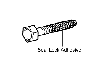
PRECOATED PARTS
-
Precoated parts are bolts and nuts that are coated with a seal lock adhesive at the factory.
-
If a precoated part is retightened, loosened or moved in any way, it must be recoated with the specified adhesive.
-
When reusing a precoated part, clean off the old adhesive and dry the part with compressed air. Then apply new seal lock adhesive appropriately to that part.
-
Some seal lock agents harden slowly. You may have to wait for the seal lock adhesive to harden.
-
-
GASKETS
-
When necessary, use a sealer on gaskets to prevent leaks.
-
-
BOLTS, NUTS AND SCREWS
-
Carefully follow all the specifications for tightening torques. Always use a torque wrench.
-
-
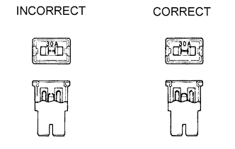
FUSES
-
When inspecting a fuse, check that the wire of the fuse is not broken.
-
When replacing fuses, be sure that a new fuse has the correct amperage rating. Do not exceed the rating or use one with a lower rating.
Illustration Symbol Part Name Abbreviation 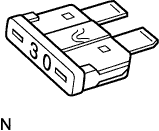
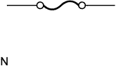
FUSE FUSE 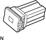
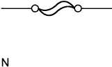
MEDIUM CURRENT FUSE M-FUSE 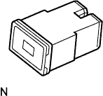
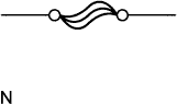
HIGH CURRENT FUSE H-FUSE 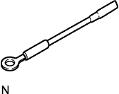
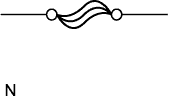
FUSIBLE LINK FL 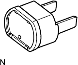
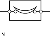
CIRCUIT BREAKER CB
-
-
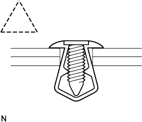
CLIPS
-
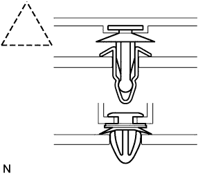
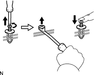
The removal and installation methods of typical clips used for vehicle body parts are shown in the table below.
Tech Tips
If clips are damaged during a procedure, always replace the damaged clips with new ones.
Shape (Example) Removal/Installation 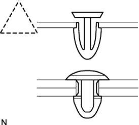
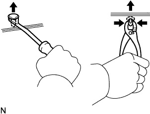
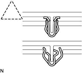
Remove clips with a clip remover or pliers.
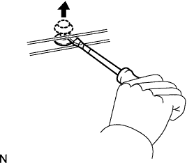
Remove clips with a clip remover or screwdriver.
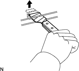
Remove clips with a wide scraper to prevent panel damage.
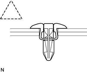
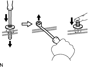
Remove clips by pushing center pin through and prying out shell.
Remove clips by unscrewing the center pin and prying out the shell.
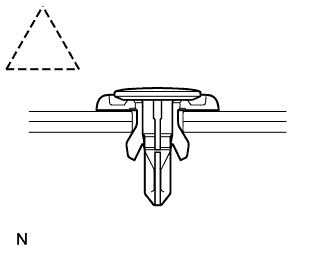
Remove the clips by prying out pin and then prying out the shell.
-
-
CLAWS
-
The removal and installation methods of typical claws used for vehicle body parts are shown in the table below.
Tech Tips
If claws are damaged during a procedure, always replace the cap or cover that has damaged claws with a new one.
Shape (Example) Illustration Procedure 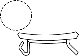
Using a screwdriver, disengage the claws and remove the cap or cover. 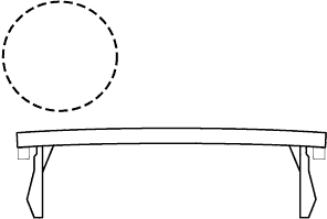
Using a screwdriver, disengage the claws and remove the cap or cover. 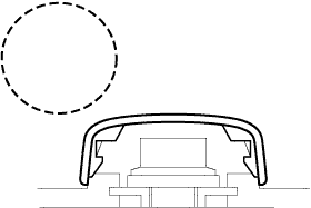
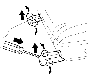
Using a screwdriver, detach the claws and remove the cap or cover.
-
-
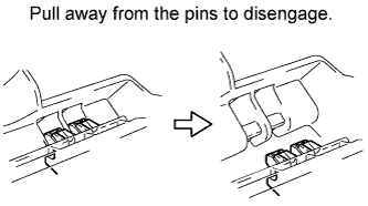
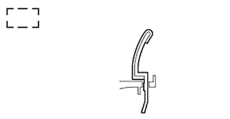
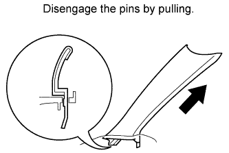
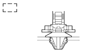
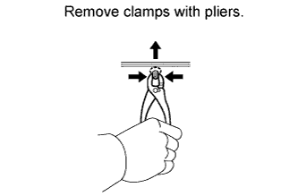
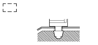
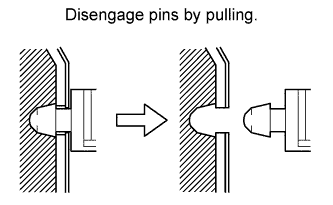
HINGES, GUIDES, CLAMPS, PINS, ETC.
-
The removal and installation methods of typical hinges, guides, clamps, and pins used for vehicle body parts are shown in the table below.
Tech Tips
If clamps are damaged during a procedure, always replace the cap or cover that has damaged clamps with a new one.
Shape (Example) Removal/Installation 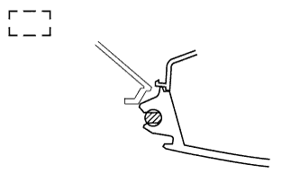
-
-
REMOVAL AND INSTALLATION OF VACUUM HOSES
-
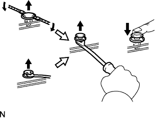
To disconnect a vacuum hose, pull and twist from the end of the hose. Do not pull from the middle of the hose as this may damage the hose.
-
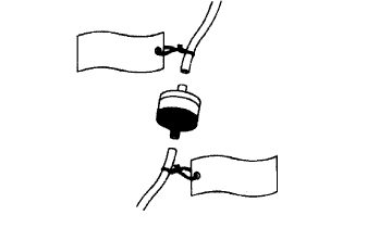
When disconnecting vacuum hoses, use tags to identify where they should be reconnected.
-
After completing any hose related repairs, double check that the vacuum hoses are properly connected. The label under the hood shows the proper layout.
-
When using a vacuum gauge, never force the hose onto a connector that is too large. If a hose has been stretched, air may leak. Use a step-down adapter if necessary.
-
-
TORQUE WHEN USING TORQUE WRENCH WITH EXTENSION TOOL
-
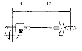
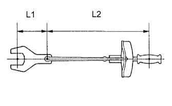
Use the formula below to calculate special torque values for situations where SST or an extension tool is combined with a torque wrench.
-
Formula
T' = (L2/(L1 + L2)) * T
T' Reading of torque wrench {N*m (kgf*cm, ft.*lbf)} T Torque {N*m (kgf*cm, ft.*lbf)} L1 Length of SST or extension tool {cm (in.)} L2 Length of torque wrench {cm (in.)}
Note
If an extension tool or SST is combined with a torque wrench and used to tighten to a torque specification in this manual, the actual torque will be excessive and parts will be damaged.
-
-
-
-
FOR VEHICLES EQUIPPED WITH SRS AIRBAG AND SEAT BELT PRETENSIONER
This vehicle is equipped with a Supplemental Restraint System (SRS).
CAUTION:
Failure to carry out the service operations in the correct sequence could cause the SRS to unexpectedly deploy during servicing and lead to serious injury. Furthermore, if a mistake is made when servicing the SRS, it is possible that the SRS may fail to operate properly. Before servicing (including removal or installation of parts, inspection or replacement), be sure to read the following section carefully.
-
GENERAL NOTICE
-
As malfunctions of the SRS are difficult to confirm, the Diagnostic Trouble Codes (DTCs) become the most important source of information when troubleshooting. When troubleshooting the SRS, always check the DTCs before disconnecting the battery.
-
Work must be started at least 90 seconds after the engine switch is turned off and after the cable is disconnected from the negative (-) battery terminal.
The SRS is equipped with a back-up power source. If work is started within 90 seconds after turning the engine switch off and disconnecting the cable from the negative (-) battery terminal, the SRS may deploy.
When the cable is disconnected from the negative (-) battery terminal, the clock and audio system memory is cleared. Before starting work, make a note of the settings of each memory system. When work is finished, reset the clock and audio system as before.
CAUTION:
Never use a back-up power source (battery or other) to avoid clearing the system memory. The back-up power source may inadvertently power the SRS and cause it to deploy.
-
In minor collisions where the SRS does not deploy, the steering pad, front passenger airbag assembly, driver side knee airbag assembly, front passenger side knee airbag assembly, front seat side airbag assembly, curtain shield airbag assembly, front seat outer belt assembly and rear seat outer belt assembly should be inspected before further use of the vehicle.
-
Never use the SRS parts from another vehicle. When replacing parts, use new parts.
-
Before repairs, remove the airbag sensor assemblies if impacts are likely to be applied to the sensor during repairs.
-
Never disassemble and attempt to repair any airbag sensor assemblies or airbag assemblies.
-
Steering pad
-
Front passenger airbag assembly
-
Driver side knee airbag assembly
-
Front Passenger side knee airbag assembly
-
Front seat side airbag assembly
-
Curtain shield airbag assembly
-
Front seat outer belt assembly with pretensioner
-
Rear seat outer belt assembly with pretensioner
-
-
Replace the airbag sensor assemblies and the airbag assemblies if: 1) damage has occurred from being dropped, or 2) cracks, dents or other defects in the case, bracket or connector are present.
-
Do not directly expose the airbag sensor assemblies or airbag assemblies to hot air or flames.
-
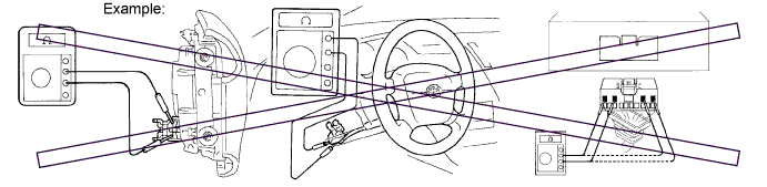
Use a voltmeter/ohmmeter with high impedance (minimum = 10 kΩ) for troubleshooting electrical circuits.
-
Information labels are attached to the SRS components. Follow the instructions on the labels.
-
After work on the SRS is completed, check the SRS warning light.
-
-
SPIRAL CABLE
-
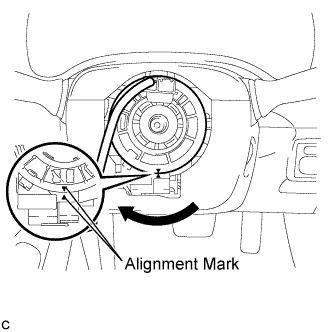
The steering wheel must be fitted correctly to the steering column with the spiral cable at the neutral position, as otherwise cable disconnection and other problems may occur. Refer to the information about correct installation of the steering wheel Click here.
-
-
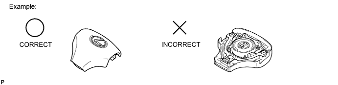
STEERING PAD
-
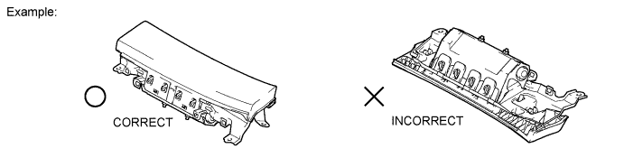
Always place a removed or new steering pad surface upward as shown in the illustration. Placing the steering pad of the pad surface facing down could cause a serious accident if the airbag deploys. Also, do not place anything on top of the steering pad.
-
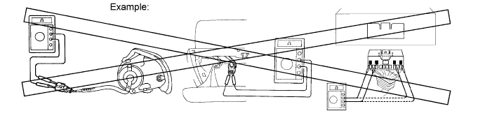
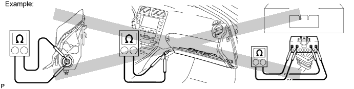
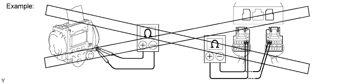
Never measure the resistance of the airbag squib. This may cause the airbag to deploy, which could cause serious injury.
-
Grease or detergents of any kind should not be applied to the steering pad.
-
Store the steering pad in an area where the ambient temperature is below 93°C (200°F), the humidity is not high and there is no electrical noise.
-
Before using an electric welder anywhere on the vehicle, disconnect the center airbag sensor assembly connectors. These connectors contain shorting springs. This feature reduces the possibility of the airbag deploying due to current entering the squib wiring.
-
When disposing of the vehicle or the steering pad by itself, the airbag should be deployed using SST before disposal Click here. Deploy the airbag in a safe place away from electrical noise.
-
-
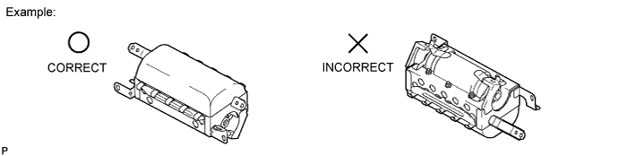
FRONT PASSENGER AIRBAG ASSEMBLY
-
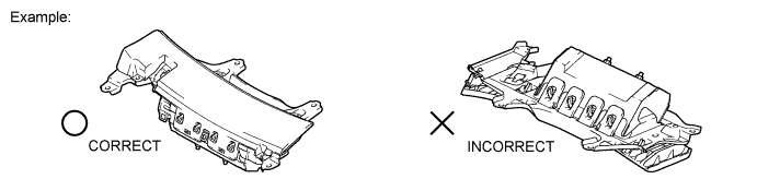
Always place a removed or new front passenger airbag assembly with the pad surface facing upward as shown in the illustration. Placing the airbag assembly with the airbag deployment direction facing down could cause a serious accident if the airbag deploys.
-
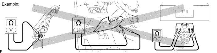
Never measure the resistance of the airbag squib. This may cause the airbag to deploy, which could cause serious injury.
-
Grease or detergents of any kind should not be applied to the front passenger airbag assembly.
-
Store the airbag assembly in an area where the ambient temperature is below 93°C (200°F), the humidity is not high and there is no electrical noise.
-
Before using an electric welder anywhere on the vehicle, disconnect the center airbag sensor assembly connectors. These connectors contain shorting springs. This feature reduces the possibility of the airbag deploying due to current entering the squib wiring.
-
When disposing of the vehicle or the airbag assembly unit by itself, the airbag should be deployed using SST before disposal Click here. Deploy the airbag in a safe place away from electrical noise.
-
-
DRIVER SIDE KNEE AIRBAG ASSEMBLY
-
Always place a removed or new driver side knee airbag assembly with the airbag deployment direction facing upward. Placing the airbag assembly with the airbag deployment direction facing downward could cause a serious accident if the airbag deploys.
-
Never measure the resistance of the airbag squib. This may cause the airbag to deploy, which could cause serious injury.
-
Grease or detergents of any kind should not be applied to the driver side knee airbag assembly.
-
Store the driver side knee airbag assembly where the ambient temperature is below 93°C (200°F), the humidity is not high and there is no electrical noise.
-
Before using an electric welder anywhere on the vehicle, disconnect the center airbag sensor assembly connectors. These connectors contain shorting springs. This feature reduces the possibility of the airbag deploying due to current entering the squib wiring.
-
When disposing of a vehicle or driver side knee airbag assembly unit by itself, the airbag should be deployed using SST before disposal Click here. Deploy in a safe place, away from electrical noise.
-
-
FRONT PASSENGER SIDE KNEE AIRBAG ASSEMBLY
-
Always place a removed or new driver side passenger side knee airbag assembly with the airbag deployment direction facing upward. Placing the airbag assembly with the airbag deployment direction facing downward could cause a serious accident if the airbag deploys.
-
Never measure the resistance of the airbag squib. This may cause the airbag to deploy, which could cause serious injury.
-
Grease or detergents of any kind should not be applied to the passenger side knee airbag assembly.
-
Store the passenger side knee airbag assembly where the ambient temperature is below 93°C (200°F), the humidity is not high and there is no electrical noise.
-
Before using an electric welder anywhere on the vehicle, disconnect the center airbag sensor assembly connectors. These connectors contain shorting springs. This feature reduces the possibility of the airbag deploying due to current entering the squib wiring.
-
When disposing of a vehicle or driver side knee airbag assembly unit by itself, the airbag should be deployed using SST before disposal Click here. Deploy in a safe place, away from electrical noise.
-
-
FRONT SEAT SIDE AIRBAG ASSEMBLY
-
Always place a removed or new front seat side airbag assembly with the airbag deployment direction facing up.
-
Never measure the resistance of the airbag squib. This may cause the airbag to deploy, which could cause serious injury.
-
Grease or detergents of any kind should not be applied to the front seat side airbag assembly.
-
Store the airbag assembly in an area where the ambient temperature is below 93°C (200°F), the humidity is not high and there is no electrical noise.
-
Before using an electric welder anywhere on the vehicle, disconnect the center airbag sensor assembly connectors. These connectors contain shorting springs. This feature reduces the possibility of the airbag deploying due to current entering the squib wiring.
-
When disposing of a vehicle or the airbag assembly unit by itself, the airbag should be deployed using SST before disposal Click here. Deploy the airbag in a safe place away from electrical noise.
-
-
CURTAIN SHIELD AIRBAG ASSEMBLY
-
Always place a removed or new curtain shield airbag assembly in a clear plastic bag, and keep it in a safe place.
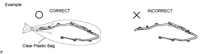
CAUTION:
The plastic bag should be disposed of after use.
Note
Never disassemble the curtain shield airbag assembly.
-
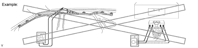
Never measure the resistance of the airbag squib. This may cause the airbag to deploy, which could cause serious injury.
-
Grease or detergents of any kind should not be applied to the curtain shield airbag assembly.
-
Store the airbag assembly in an area where the ambient temperature is below 93°C (200°F), the humidity is not high and there is no electrical noise.
-
Before using an electric welder anywhere on the vehicle, disconnect the center airbag sensor assembly connectors. These connectors contain shorting springs. This feature reduces the possibility of the airbag deploying due to current entering the squib wiring.
-
When disposing of a vehicle or the airbag assembly unit by itself, the airbag should be deployed using SST before disposal Click here. Deploy the airbag in a safe place away from electrical noise.
-
-
FRONT SEAT OUTER BELT ASSEMBLY (SEAT BELT PRETENSIONER)
-
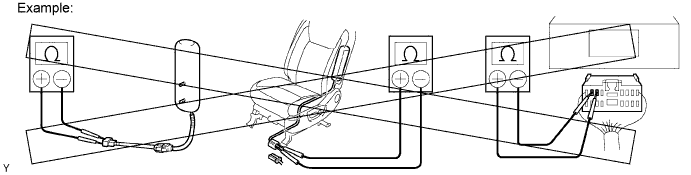
Never measure the resistance of the front seat outer belt assembly. This may cause the pretensioner of the front seat outer belt assembly to activate, which could cause serious injury.
-
Never disassemble the front seat outer belt assembly.
-
Never install the front seat outer belt assembly on another vehicle.
-
Store the front seat outer belt assembly in an area where the ambient temperature is below 80°C (176°F), the humidity is not high and there is no electrical noise.
-
Before using an electric welder anywhere on the vehicle, disconnect the center airbag sensor assembly connectors. These connectors contain shorting springs. This feature reduces the possibility of the airbag deploying due to current entering the squib wiring.
-
When disposing of a vehicle or the front seat outer belt assembly unit by itself, the front seat outer belt assembly should be activated before disposal Click here. Activate the front seat outer belt assembly in a safe place away from electrical noise.
-
As the front seat outer belt assembly is hot after being activated, allow some time for it to cool down sufficiently before disposal. Never apply water to cool down the front seat outer belt assembly.
-
Grease, detergents, oil or water should not be applied to the front seat outer belt assembly.
-
-
REAR SEAT OUTER BELT ASSEMBLY (SEAT BELT PRETENSIONER)
-
Never measure the resistance of the rear seat outer belt assembly. This may cause the pretensioner of the rear seat outer belt assembly to activate, which could cause serious injury.
-
Never disassemble the rear seat outer belt assembly.
-
Never install the rear seat outer belt assembly on another vehicle.
-
Store the rear seat outer belt assembly in an area where the ambient temperature is below 80°C (176°F), the humidity is not high and there is no electrical noise.
-
Before using an electric welder anywhere on the vehicle, disconnect the center airbag sensor assembly connectors. These connectors contain shorting springs. This feature reduces the possibility of the airbag deploying due to current entering the squib wiring.
-
When disposing of a vehicle or the rear seat outer belt assembly unit by itself, the rear seat outer belt assembly should be activated before disposal Click here. Activate the rear seat outer belt assembly in a safe place away from electrical noise.
-
As the rear seat outer belt assembly is hot after being activated, allow some time for it to cool down sufficiently before disposal. Never apply water to cool down the rear seat outer belt assembly.
-
Grease, detergents, oil or water should not be applied to the rear seat outer belt assembly.
-
-
CENTER AIRBAG SENSOR ASSEMBLY
-
Never reuse a center airbag sensor assembly that has been involved in a collision where the SRS has deployed.
-
The connectors to the center airbag sensor assembly should be connected or disconnected with the sensor installed to the vehicle. If the connectors are connected or disconnected while the center airbag sensor assembly is not installed, the SRS may activate.
-
Work must be started at least 90 seconds after the engine switch is turned off and the cable is disconnected from the negative (-) battery terminal, even if only loosening the bolts of the center airbag sensor assembly.
-
-
WIRE HARNESS AND CONNECTOR
-
All the connectors in the system are a standard yellow color. If an SRS wire harness has an open circuit or the connector is broken, replace it.
-
-
-
ELECTRONIC CONTROL
-
REMOVAL AND INSTALLATION OF BATTERY TERMINAL
Note
-
Certain systems need to be initialized after reconnecting the cable to the negative (-) battery terminal.
-
Before starting the engine, make sure that the ground point is installed to the body with the bolts.
-
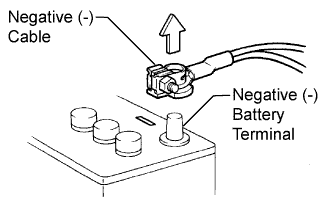
Before performing electrical work, disconnect the cable from the negative (-) battery terminal to prevent component and wire damage caused by accidental short circuits.
-
When disconnecting the cable, turn the engine switch and headlight switch off and loosen the cable nut completely. Perform these operations without twisting or prying the cable. Then disconnect the cable.
-
Clock settings, radio settings, audio system memory, DTCs and other data are cleared when the cable is disconnected from the negative (-) battery terminal. Write down any necessary data before disconnecting the cable.
-
-
HANDLING OF ELECTRONIC PARTS
-
Do not open the cover or case of the ECU unless absolutely necessary. If the IC terminals are touched, the IC may be rendered inoperative by static electricity.
-
Do not pull the wires when disconnecting electronic connectors. Pull the connector itself.
-
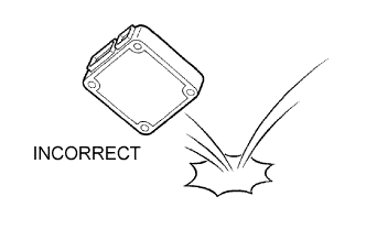
Do not drop electronic components, such as sensors or relays. If they are dropped on a hard surface, they should be replaced.
-
When cleaning the engine with steam, protect the electronic components, air filter and emission-related components from water.
-
Never use an impact wrench to remove or install temperature switches or temperature sensors.
-
When measuring the resistance between terminals of a wire connector, insert the tester probe carefully to prevent terminals from bending.
-
-
-
REMOVAL AND INSTALLATION OF FUEL CONTROL PARTS
-
PLACE FOR REMOVING AND INSTALLING FUEL SYSTEM PARTS
-
Work in a location with good air ventilation that does not have welders, grinders, drills, electric motors, stoves, or any other ignition sources.
-
Never work in a pit or near a pit as vaporized fuel will collect in those places.
-
-
REMOVING AND INSTALLING FUEL SYSTEM PARTS
-
Prepare a fire extinguisher before starting the operation.
-
To prevent static electricity, install a ground wire to the fuel changer, vehicle and fuel tank, and do not spray the surrounding area with water. Be careful when performing work in this area, as the work surface will become slippery. Do not clean up gasoline spills with water, as this may cause the gasoline to spread, and possibly create a fire hazard.
-
Avoid using electric motors, work lights and other electric equipments that can cause sparks or high temperatures.
-
Avoid using iron hammers as they may create sparks.
-
Dispose of fuel-contaminated cloth separately using a fire resistant container.
-
-
-
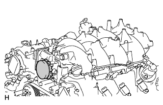
REMOVAL AND INSTALLATION OF ENGINE INTAKE PARTS
-
If any metal particles enter intake system parts, this may damage the engine.
-
When removing and installing intake system parts, cover the openings of the removed parts and engine openings. Use adhesive tape or other suitable materials.
-
When installing intake system parts, check that no metal particles have entered the engine or installed parts.
-
-
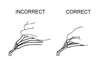
HANDLING OF HOSE CLAMPS
-
Before removing a hose, check the clamp position so that it can be reinstalled in the same position.
-
Replace any deformed or dented clamps with new ones.
-
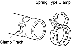
When reusing a hose, attach the clamp on the clamp track portion of the hose.
-
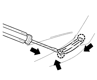
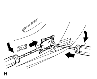
For a spring type clamp, it may be necessary to spread the tabs slightly after installation by pushing in the direction of the arrows as shown in the illustration.
-
-
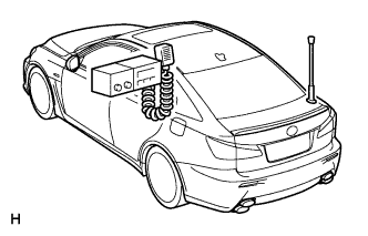
FOR VEHICLES EQUIPPED WITH MOBILE COMMUNICATION SYSTEMS
-
Install the antenna as far away from the ECU and sensors of the vehicle electronic systems as possible.
-
Install an antenna feeder at least 20 cm (7.87 in.) away from the ECU and sensors of the vehicle electronic systems. For details about the ECU and sensor locations, refer to the section on the applicable components.
-
Keep the antenna and feeder separate from other wirings as much as possible. This will prevent signals sent from the communication equipment from affecting vehicle equipment and vice-versa.
-
Check that the antenna and feeder are correctly adjusted.
-
Do not install high-powered mobile communication system.
-
-
HEADLIGHT INSPECTION OR MAINTENANCE
-
When the headlight dimmer switch assembly is set to HEAD, do not touch the discharge headlight's high-voltage socket area.
Note
When performing inspection or maintenance, the discharge headlight precautions must be followed.
-
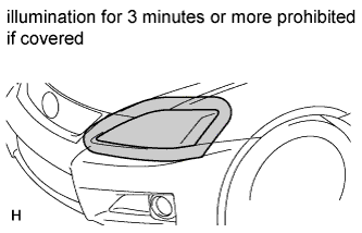
When the headlights are illuminated, do not cover the headlights for 3 minutes or more.
Note
As the headlight's outer lens is made of resin, the resulting heat created when covering the headlight for an extended period of time may deform the headlight.
-
-
FOR VEHICLES EQUIPPED WITH TRACTION CONTROL (TRC) AND VEHICLE STABILITY CONTROL (VSC) SYSTEMS
-
NOTICES FOR WHEN TESTING WITH 2-WHEEL DRUM TESTER
-
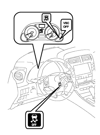
When testing with a 2-wheel drum tester such as a speedometer tester, a combination speedometer and brake tester, or a chassis dynamometer, enter inspection mode, or switch to VSC OFF mode to turn TRC and VSC operation off.
Note
-
If the vehicle is tested in normal mode on the drum tester, TRC and VSC operation may cause the vehicle to jump out from the drum tester.
-
When switching to VSC OFF mode, the VSC OFF switch must be held for 3 seconds or more with the vehicle stopped. TRC and VSC operation must both be turned off before beginning testing.
-
During VSC OFF mode, the combination meter's SLIP indicator light and VSC OFF indicator light illuminate.
-
Secure the vehicle in place with chains for safety.
-
-
-
Activating inspection mode (Not using the intelligent tester)
Tech Tips
-
Perform steps "C" to "H" within 30 seconds.
-
Perform steps "F" and "G" within 15 seconds each.
-
Ensure that the engine switch is off and the engine is stopped (Step "A").
-
Make sure that the shift lever is in P (Step "B").
-
Start the engine (Step "C").
-
Apply the parking brake by pressing the parking brake pedal (Step "D").
-
Depress and release the brake pedal twice (Step "E").
-
While holding the brake pedal down, release and apply the parking brake twice (Step "F").
-
With the parking brake applied, depress and release the brake pedal twice (Step "G").
-
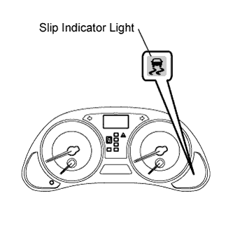
Check if the SLIP indicator light comes on (Step "H").
Tech Tips
-
If the SLIP indicator light does not come on in step "H", repeat the steps from "A" to "H".
-
Turning the engine switch off ends inspection mode.
-
-
-
Activating inspection mode (Using the intelligent tester)
-
Ensure that the engine switch is off and the engine is stopped (Step "A").
-
Make sure that the shift lever is in P (Step "B").
-
Connect the intelligent tester to the DLC3 (Step "C").
-
Start the engine (Step "D").
-
Turn the intelligent tester switch on (Step "E").
-
Enter the following menus: Chassis / ABS/VSC/TRC / Inspection Mode (Step "F").
-
Check if the SLIP indicator light comes on (Step "G").
Tech Tips
-
If the SLIP indicator light does not come on in step "G", repeat the steps from "A" to "G".
-
Turning the engine switch off ends inspection mode.
-
-
-
NOTICES FOR VSC RELATED PROCEDURES
-
For VSC related parts, adjustments are required after removal and installation. Therefore, perform removal and installation only when necessary.
-
When performing VSC related procedures, be sure to strictly follow the preparation and completion procedures.
-
When performing removal and installation or replacement of VSC related parts, first disconnect the cable from the negative (-) battery terminal.
-
-
-
FOR VEHICLES EQUIPPED WITH CATALYTIC CONVERTER
CAUTION:
If a large amount of unburned gasoline or gasoline vapors flow into the converter, it may cause converter overheating and create a fire hazard. To prevent this, observe the following precautions:
-
Use only unleaded gasoline.
-
Avoid idling the engine for more than 20 minutes.
-
Avoid performing unnecessary spark tests.
-
Perform a spark test only when absolutely necessary. Perform this test as rapidly as possible.
-
While testing, never race the engine unless instructed.
-
-
Avoid a prolonged engine compression measurement. Engine compression measurements must be performed as rapidly as possible.
-
Do not run the engine when the fuel tank is nearly empty. This may cause the engine to misfire and create an extra load on the converter.
-
-
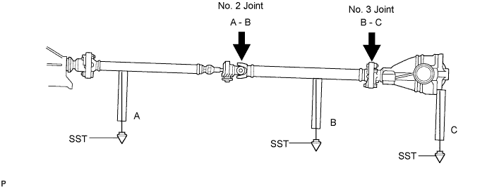
INSPECTION AND ADJUSTMENT OF JOINT ANGLE DURING REMOVAL AND INSTALLATION OF PROPELLER SHAFT
-
When performing operations which involve the removal and installation of the propeller shaft, always check the joint angle. Make adjustments if necessary Click here.
-