NAVIGATION SYSTEM (for HDD) OPERATION CHECK

-
CHECK SYSTEM NORMAL CONDITION
-
If the symptom is applicable to any of the following, it is intended behavior, and not a malfunction.
Symptom Answer A longer route than expected is chosen. Depending on the road conditions, the display and navigation module display may determine that a longer route is quicker. Even when distance priority is high, the shortest route is not shown. Some routes may not be advised due to safety concerns. When the vehicle is put into motion immediately after the engine starts, the navigation system deviates from the current position. If the vehicle starts before the navigation system activates, the system may not react. When driving on certain types of roads, especially new roads, the vehicle position deviates from the current position. When the vehicle is driving on new roads not available on the map data from the hard disk drive, the system attempts to match it to another nearby road, causing the position mark to deviate. -
The following symptoms are not malfunctions, but are caused by errors inherent in the GPS, gyro sensor, speed sensor or display and navigation module display.
-
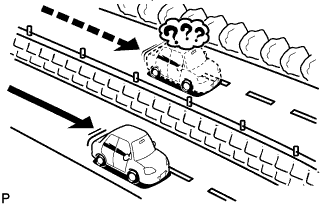
The current position mark may be displayed on a nearby parallel road.
-
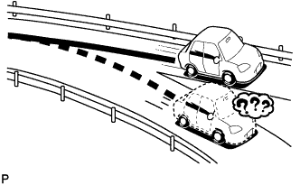
Immediately after a fork in the road, the current vehicle position mark may be displayed on the wrong road.
-
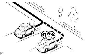
When the vehicle turns right or left at an intersection, the current vehicle position mark may be displayed on a nearby parallel road.
-
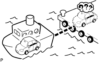
When the vehicle is carried, such as on a ferry, and the vehicle itself is not driving, the current vehicle position mark may be displayed in the position where the vehicle was until a measurement can be performed by GPS.
-
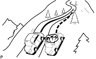
When the vehicle travels on a steep hill, the current vehicle position mark may deviate from the correct position.
-
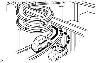
When the vehicle makes a continuous turn (e.g. 360, 720, 1080 degrees), the current vehicle position mark may deviate from the correct position.
-
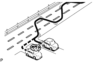
When the vehicle moves erratically, such as constant lane changes, the current vehicle position mark may deviate from the correct position.
-
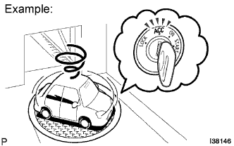
When the engine switch is turned on (ACC or IG) on a turntable before parking, the current vehicle position mark may not indicate the correct direction. The same will occur when the vehicle comes out of the parking garage.
-
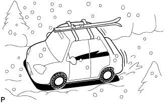
When the vehicle travels on a snowy road or a mountain path with tire chains installed or using a spare tire, the current vehicle position mark may deviate from the correct position.
-
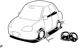
When the tires are changed, the current vehicle position mark may deviate from the correct position.
Tech Tips
-
A change in tire diameter may cause a speed sensor error.
-
Performing "tire change" in calibration mode will allow the system to correct the current vehicle position faster.
-
-
-
-
CHECK HARD DISK DRIVE
Tech Tips
-
Check the hard disk drive (HDD) built into the display and navigation module display.
-
Illustrations may differ from the actual vehicle screen depending on the device settings and options. Therefore, some detailed areas may not be shown exactly the same as on the actual vehicle screen.
-
Enter diagnostic mode Click here.
-
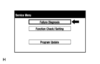
Select "Failure Diagnosis" from the "Service Menu" screen.
-
Hard disk drive check
-
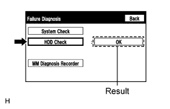
Select "HDD Check" to start the HDD check.
-
Check that the result is displayed when the HDD check is completed.
Screen Description Result Description Checking While the check is in progress OK Hard disk drive is normal NG Hard disk drive is malfunctioning Tech Tips
-
After selecting "HDD Check", it may take a while until the result is displayed.
-
If the cabin temperature is -20°C (-4°F) or lower, or 65°C (149°F) or higher, the HDD may not operate normally, and "NG" may be shown on the display. Make sure to perform the inspection with the cabin at an appropriate temperature.
-
If "NG" is displayed even when the cabin temperature is appropriate, replace the HDD with a new one.
-
-
-
-
CHECK PANEL & STEERING SWITCH
Tech Tips
-
The display and navigation module display panel switches, radio receiver assembly panel switches and steering switch are checked in the following procedure.
-
Illustrations may differ from the actual vehicle screen depending on the device settings and options. Therefore, some detailed areas may not be shown exactly the same as on the actual vehicle screen.
-
Enter diagnostic mode Click here.
-
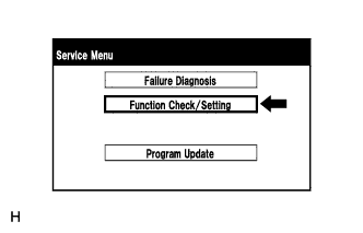
Select "Function Check/Setting" from the "Service Menu" screen.
-
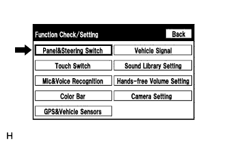
Select "Panel & Steering Switch" from the "Function Check/Setting" screen.
-
Panel & Steering Switch Check Mode
-
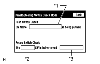
Operate each switch and check that the switch names and condition are correctly displayed.
Screen Description Display Content *1: Name of switch being pushed
-
Name of the pushed switch is displayed.
-
If more than one switch is pressed, "MULTIPLE" will be displayed.
*2: Rotary switch name Name of the rotary switch is displayed. *3: Rotary switch direction Direction of the rotary switch is displayed. -
-
-
-
CHECK TOUCH SWITCH
Tech Tips
-
The touch switches on the screen are checked in the following procedure.
-
Illustrations may differ from the actual vehicle screen depending on the device settings and options. Therefore, some detailed areas may not be shown exactly the same as on the actual vehicle screen.
-
Enter diagnostic mode Click here.
-
Select "Function Check/Setting" from the "Service Menu" screen.
-
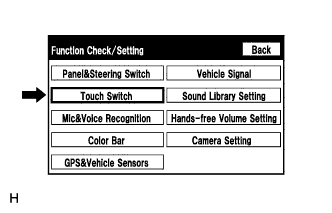
Select "Touch Switch" from the "Function Check/Setting" screen.
-
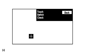
Touch Switch Check
-
Touch the display anywhere in the open area to perform the check when the "Touch Switch Check" screen is displayed.
Tech Tips
-
A "+" mark is displayed where the display is touched.
-
The "+" mark remains on the display even after the finger is removed.
-
-
-
-
CHECK MIC & VOICE RECOGNITION
Tech Tips
-
The microphone and microphone input level are checked in the following procedure.
-
Illustrations may differ from the actual vehicle screen depending on the device settings and options. Therefore, some detailed areas may not be shown exactly the same as on the actual vehicle screen.
-
Enter diagnostic mode Click here.
-
Select "Function Check/Setting" from the "Service Menu" screen.
-
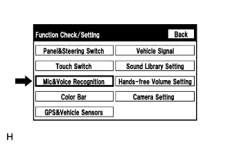
Select "Mic & Voice Recognition" from the "Function Check/Setting" screen.
-
Microphone & Voice Recognition Check
-
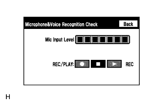
When speaking into the microphone, check that the microphone input level meter changes according to the input level.
-
Select the recording switch and perform voice recording.
Tech Tips
Select the recording switch with the blower motor of the air conditioning system stopped. If an outlet of the air conditioning system is facing the microphone, noise may be recorded.
-
Check that the recording indicator remains on while recording and that the recording can be played normally.
Tech Tips
-
For details of this function, refer to Diagnosis Display Detailed Description in System Description Click here.
-
This function is controlled by the display and navigation module display (built-in navigation ECU).
-
-
-
-
CHECK COLOR BAR
Tech Tips
-
The display color on the screen is checked in the following procedure.
-
Illustrations may differ from the actual vehicle screen depending on the device settings and options. Therefore, some detailed areas may not be shown exactly the same as on the actual vehicle screen.
-
Enter diagnostic mode Click here.
-
Select "Function Check/Setting" from the "Service Menu" screen.
-
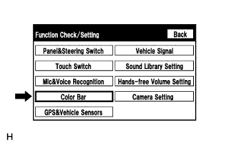
Select "Color Bar" from the "Function Check/Setting" screen.
-
Color Bar Check Mode
-
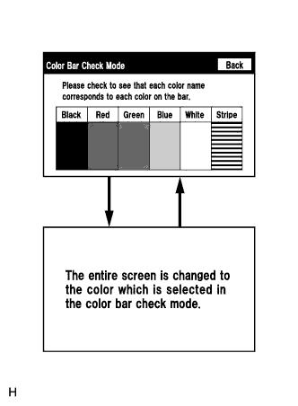
Select a color bar from the "Color Bar Check Mode" screen.
-
Check the display color.
Tech Tips
-
The entire screen turns to the color or stripe selected.
-
Touching the display will return to the "Color Bar Check Mode" screen.
-
-
-
-
CHECK GPS & VEHICLE SENSORS
Tech Tips
-
GPS information, vehicle signals and sensor signals are checked in the following procedure.
-
Illustrations may differ from the actual vehicle screen depending on the device settings and options. Therefore, some detailed areas may not be shown exactly the same as on the actual vehicle screen.
-
Enter diagnostic mode Click here.
-
Select "Function Check/Setting" from the "Service Menu" screen.
-
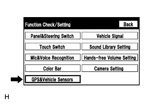
Select "GPS & Vehicle Sensors" from the "Function Check/Setting" screen.
-
GPS Information
-
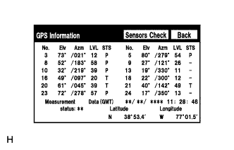
When "GPS Information screen" is displayed, check the GPS conditions.
Tech Tips
-
This screen is updated once per second when input signals to the vehicle are changed.
-
For details of this function, refer to Diagnosis Display Detailed Description in System Description Click here.
-
-
-
Select "Sensors Check" from the "GPS information" screen.
-
Vehicle Sensors
-
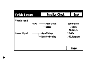
Check all the signals and sensors when vehicle signal information is displayed.
Tech Tips
-
This screen is updated once per second when input signals to the vehicle are changed.
-
This screen displays vehicle signals input to the display and navigation module display (built-in navigation ECU).
-
For details of this function, refer to Diagnosis Display Detailed Description in System Description Click here.
-
-
-
-
CHECK VEHICLE SIGNAL
Tech Tips
-
Vehicle signals received by the display and navigation module display are checked in the following procedure.
-
Illustrations may differ from the actual vehicle screen depending on the device settings and options. Therefore, some detailed areas may not be shown exactly the same as on the actual vehicle screen.
-
Enter diagnostic mode Click here.
-
Select "Function Check/Setting" from the "Service Menu" screen.
-
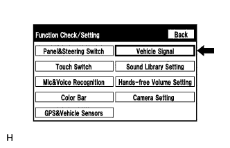
Select "Vehicle Signal" from the "Function Check/Setting" screen.
-
Vehicle Signal Check Mode
-
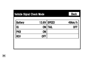
When the "Vehicle Signal Check Mode" screen is displayed, check all the vehicle signal conditions.
Tech Tips
-
Only conditions having inputs are displayed.
-
This screen displays vehicle signals input to the display and navigation module display (built-in navigation ECU).
-
For details of this function, refer to Diagnosis Display Detailed Description in System Description Click here.
-
-
-
-
CHECK SOUND LIBRARY SETTING (w/ SOUND LIBRARY FUNCTION)
Tech Tips
-
It is possible to turn the sound library function on and off and check the operation of the sound library function.
-
Illustrations may differ from the actual vehicle screen depending on the device settings and options. Therefore, some detailed areas may not be shown exactly the same as on the actual vehicle screen.
-
Enter diagnostic mode Click here.
-
Select "Function Check/Setting" from the "Service Menu" screen.
-
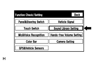
Select "Sound Library Setting" from the "Function Check/Setting" screen.
-
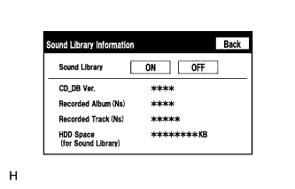
Sound Library Information
Tech Tips
Refer to the audio and visual system (w/ navigation system) for further information Click here.
-
-
CHECK HANDS-FREE VOLUME SETTING
Tech Tips
-
The hands-free volume of a "Bluetooth" compatible phone can be adjusted using the following procedure.
-
Illustrations may differ from the actual vehicle screen depending on the device settings and options. Therefore, some detailed areas may not be shown exactly the same as on the actual vehicle screen.
-
Enter diagnostic mode Click here.
-
Select "Function Check/Setting" from the "Service Menu" screen.
-
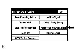
Select "Hands-free Volume Setting" from the "Function Check/Setting" screen.
-
Hands-free Volume Setting
-
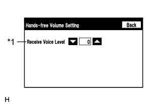
Check the hands-free volume level.
Screen Description Display Content *1: Receive voice level adjustment Adjusts voice level received from "Bluetooth" compatible phones Note
Sound quality may deteriorate when the receive voice level is changed more than necessary. For this reason, check that the receive voice quality is still acceptable after changing this setting.
-
-
-
CHECK CAMERA SETTING (w/ PARKING ASSIST MONITOR SYSTEM)
Tech Tips
-
It is possible to make adjustments and check the signals received by the parking assist ECU.
-
Illustrations may differ from the actual vehicle screen depending on the device settings and options. Therefore, some detailed areas may not be shown exactly the same as on the actual vehicle screen.
-
Enter diagnostic mode Click here.
-
Select "Function Check/Setting" from the "Service Menu" screen.
-
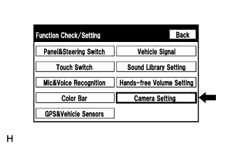
Select "Camera Setting" from the "Function Check/Setting" screen.
-
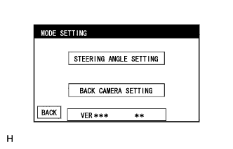
MODE SETTING
Tech Tips
Refer to the parking assist monitor system for further information Click here.
-