NAVIGATION SYSTEM (for DVD) TC Terminal Circuit
DESCRIPTION
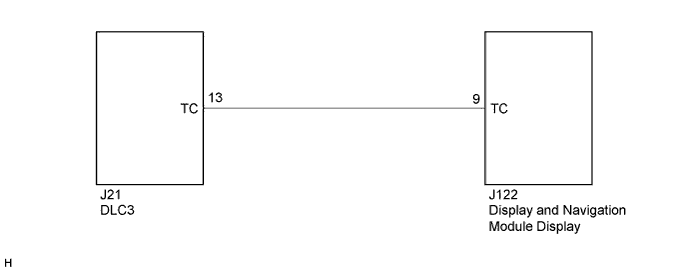
The display and navigation module display is connected to the DLC3 by the vehicle wire harness.
Tech Tips
If there is a short circuit to ground in the wire between the display and navigation module display and DLC3, the diagnosis mode screen will be displayed on the multi-display immediately after the engine switch is turned on (ACC).
WIRING DIAGRAM
INSPECTION PROCEDURE
PROCEDURE
-
CHECK HARNESS AND CONNECTOR (DLC3 - DISPLAY AND NAVIGATION MODULE DISPLAY)
-
Disconnect the J122 display and navigation module display connector.
-
Measure the resistance according to the value(s) in the table below.
Standard Resistance Tester Connection Condition Specified Condition J122-9 (TC) - Body ground Always 10 kΩ or higher
NG 
REPAIR OR REPLACE HARNESS OR CONNECTOR
OK 
PROCEED TO NEXT SUSPECTED AREA SHOWN IN PROBLEM SYMPTOMS TABLE Click here
-