NAVIGATION SYSTEM (for DVD) TERMINALS OF ECU

-
DISPLAY AND NAVIGATION MODULE DISPLAY
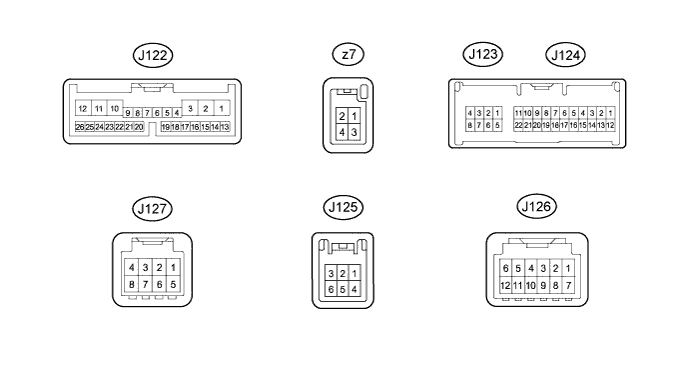
Terminal No.
(Symbol)
Wiring Color Terminal Description Condition Specified Condition J122-1 (+B1) - J122-10 (GND1) Y - W-B Power source (Back-up) Always 11 to 14 V J122-2 (ACC) - J122-10 (GND1) BE - W-B Power source (ACC) Engine switch off Below 1 V Engine switch on (ACC) 11 to 14 V J122-3 (IG) - J122-10 (GND1) B - W-B Power source (IG) Engine switch off Below 1 V Engine switch on (IG) 11 to 14 V J122-4 (MACC) - J122-10 (GND1) W - W-B Microphone AMP power supply Engine switch off Below 1 V Engine switch on (IG) 4.5 to 5.5 V J122-5 (MIN+) - J122-10 (GND1) R - W-B Microphone voice signal See "Microphone & Voice Recognition Check" Click here
- J122-6 (MIN-) - Body ground B - Body ground Microphone voice signal See "Microphone & Voice Recognition Check" Click here
- J122-7 (SGND) - Body ground Shield - Body ground Shield ground Always Below 1 V J122-9 (TC) - J122-10 (GND1) V - W-B Diagnosis signal Engine switch on (IG) 9 to 14 V J122-11 (ILL-) - J122-10 (GND1) W - W-B Illumination signal Light control switch off Below 1 V Light control switch tail or head (Light intensity is not max. or min.) Pulse generation J122-12 (ILL+) - J122-10 (GND1) G - W-B Illumination signal Light control switch off Below 1 V Light control switch tail or on 11 to 14 V J122-16 (REV) - J122-10 (GND1) L - W-B Reverse signal See "Vehicle Signal Check Mode" Click here
- J122-17 (PKB) - J122-10 (GND1) R - W-B Parking brake signal See "Vehicle Signal Check Mode" Click here
- J122-18 (SPD) - J122-10 (GND1) P - W-B Vehicle speed signal See "Vehicle Signal Check Mode" Click here
- J122-20 (SNS2) - J122-10 (GND1) V - W-B Voice recognition and microphone connection detection signal Always Below 1 V J122-21 (CANH) SB CAN communication signal - - J122-22 (CANL) W CAN communication signal - - J122-23 (SWG) - Body ground GR - Body ground Steering pad switch signal Always Below 1 V J122-24 (SW2) - J122-23 (SWG) L - GR Steering pad switch signal No switch pushed
→ MODE switch pushed
→ On Hook switch pushed
→ Off Hook switch pushed
→ Voice switch pushed
4.44 to 5.43 V
→ 0.45 to 0.65 V
→ 1.19 to 1.49 V
→ 2.09 to 2.54 V
→ 3.2 to 3.88 V
J122-25 (SW1) - J122-23 (SWG) SB - GR Steering pad switch signal No switch pushed
→ Seek+ switch pushed
→ Seek- switch pushed
→ Volume+ switch pushed
→ Volume- switch pushed
4.44 to 5.43 V
→ 0.45 to 0.65 V
→ 1.19 to 1.49 V
→ 2.09 to 2.54 V
→ 3.2 to 3.88 V
J124-1 (TX1+)*1 BR AVC-LAN communication signal - - J124-2 (TX1-)*1 R AVC-LAN communication signal - - J124-5 (V+) - J122-10 (GND1)*2 R - W-B Television camera image signal Engine switch on (IG)
Shift lever in R
Camera lens not covered, displaying an image
Pulse generation
(Refer to waveform 1)
Engine switch on (IG)
Shift lever in R
Camera lens covered, blacking out screen
Pulse generation
(Refer to waveform 2)
J124-6 (CA+) - J122-10 (GND1)*2 B - W-B Television camera power supply Engine switch on (IG)
Shift lever in R
5.5 to 7 V J124-9 (VV+) - J122-10 (GND1) R - W-B Display signal DVD playing A waveform synchronized with display signals is output.
(Refer to waveform 1)
J124-12 (TX2+) SB AVC-LAN communication signal - - J124-13 (TX2-) BE AVC-LAN communication signal - - J124-16 (V-) - J122-10 (GND1)*2 W - W-B Ground Always Below 1 V J124-17 (CGND) - Body ground*2 Shield - Body ground Shield ground Always Below 1 V J124-20 (VV-) - J122-10 (GND1) G - W-B Ground Always Below 1 V J123-1 (MI+) W MOST communication signal - - J123-2 (SLDI) - J122-10 (GND1) BR - W-B Shield ground Always Below 1 V J123-3 (MO+) W MOST communication signal - - J123-5 (MI-) B MOST communication signal - - J123-6 (SLDO) - J122-10 (GND1) BR - W-B Shield ground Always Below 1 V J123-7 (MO-) B MOST communication signal - - J123-8 (WUO) - J122-10 (GND1) B - W-B MOST communication wake-up signal Engine switch on (ACC) 4.5 V or higher Engine switch off Below 1 V J127-1 (AGND) - Body ground Shield - Body ground Shield ground Always Below 1 V J127-3 (VAR+) - J127-7 (VA-) W - B Sound signal (Right) USB audio device playing (When stereo jack adapter used) A waveform synchronized with sounds is output. J127-4 (VAL+) - J127-7 (VA-) R - B Sound signal (Left) USB audio device playing (When stereo jack adapter used) A waveform synchronized with sounds is output. J127-7 (VA-) - J122-10 (GND1) B - W-B Sound signal ground Always Below 1 V J125-6 (SEUC) - J122-10 (GND1) LG - W-B Security indicator signal Security indicator operation 11 to 14 V J126-7 (GND) - Body ground W - Body ground Ground Always Below 1 V J126-9 (TXM+) R AVC-LAN communication signal - - J126-10 (TXM-) G AVC-LAN communication signal - - J126-11 (ACC) - J122-10 (GND1) L - W-B Accessory (ON) Engine switch on (ACC) 11 to 14 V Engine switch off Below 1 V J126-12 (+B) - J122-10 (GND1) B - W-B Battery Always 11 to 14 V z7-1 (+B2) - J122-10 (GND1) Y - W-B Battery Always 11 to 14 V z7-2 (ACC) - J122-10 (GND1) R - W-B Accessory (ON) Engine switch on (ACC) 11 to 14 V Engine switch off Below 1 V z7-4 (G) - J122-10 (GND1) B - W-B Ground Always Below 1 V
-
*1: w/ Parking Assist Monitor System
-
*2: w/ Rear View Monitor System
-
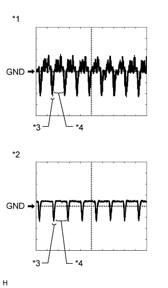
Reference (Oscilloscope waveform):
-
Waveform 1 (camera lens not covered, displaying an image)
Item Content Measurement terminal J124-5 (V+) - J122-10 (GND1) Measurement setting 200 mV/DIV., 50 μsec./DIV. Condition Engine switch on (IG), shift lever in R Tech Tips
The video waveform changes according to the image from the television camera assembly.
-
Waveform 2 (camera lens is covered, blacking out the screen)
Item Content Measurement terminal J124-5 (V+) - J122-10 (GND1) Measurement setting 200 mV/DIV., 50 μsec./DIV. Condition Engine switch on (IG), shift lever in R Tech Tips
The video waveform changes according to the image that the television camera assembly projects.
-
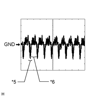
Text in Illustration *1 Waveform 1 (camera lens not covered, displaying an image) *2 Waveform 2 (camera lens is covered, blacking out the screen) *3 Synchronization Signal *4 Video Waveform *5 Synchronization Signal *6 Video Waveform Waveform 3
Item Content Measurement Terminal J124-9 (VV+) - J122-10 (GND1) Measurement Setting 200 mV/DIV., 10 μs/DIV. Condition DVD is playing Tech Tips
The video waveform changes according to the image input from the radio receiver assembly to the display and navigation module display, but the synchronization signal does not change.
-
-
-
NAVIGATION MODULE BOARD

Terminal No.
(Symbol)
Wiring Color Terminal Description Condition Specified Condition z9-1 (+B) - z9-5 (GND1) Y - B Battery Always 11 to 14 V z9-3 (ACC1) - z9-5 (GND1) R - B Power source (ACC) Engine switch off Below 1 V Engine switch on (ACC) 11 to 14 V z9-5 (GND1) - Body ground B - Body ground Ground Always Below 1 V -
NETWORK GATEWAY ECU

Terminal No.
(Symbol)
Wiring Color Terminal Description Condition Specified Condition J76-1 (IG) - J76-24 (GND) B - W-B Power source (IG) Engine switch on (IG) 11 to 14 V Engine switch off Below 1 V J76-2 (ACC) - J76-24 (GND) BE - W-B Accessory (ON) Engine switch on (ACC) 11 to 14 V Engine switch off Below 1 V J76-3 (MPD1) GR MPX communication signal - - J76-4 (MPI1) BR MPX communication signal - - J76-6 (GTX+) SB AVC-LAN communication signal - - J76-10 (BATT) - J76-24 (GND) LG - W-B Battery Always 11 to 14 V J76-12 (MPD2) GR MPX communication signal - - J76-13 (MPI2) BR MPX communication signal - - J76-17 (CA1H) B CAN communication signal - - J76-18 (CA1L) W CAN communication signal - - J76-21 (GTX-) BE AVC-LAN communication signal - - J76-24 (GND) - Body ground W-B - Body ground Ground Always Below 1 V -
RADIO RECEIVER ASSEMBLY Click here
-
STEREO COMPONENT AMPLIFIER ASSEMBLY Click here
-
MULTI-MEDIA INTERFACE ECU Click here
-
PARKING ASSIST ECU (w/ Parking Assist Monitor System) Click here