NAVIGATION SYSTEM RDS-TMC Signal Circuit between Radio Receiver and Navigation ECU
DESCRIPTION
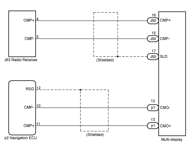
Traffic information received by the radio receiver is transmitted to the navigation ECU via this circuit.
If an open or short occurs in this circuit, RDS-TMC information will not be updated or the RDS-TMC will not operate normally.
WIRING DIAGRAM
INSPECTION PROCEDURE
PROCEDURE
-
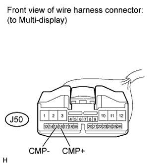
CHECK HARNESS AND CONNECTOR (MULTI-DISPLAY - RADIO RECEIVER)
-
Disconnect the multi-display connector and radio receiver connector.
-
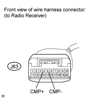
Measure the resistance according to the value(s) in the table below.
Standard Resistance Tester Connection Condition Specified Condition J63-4 (CMP+) - J50-16 (CMP+) Always Below 1 Ω J63-5 (CMP-) - J50-15 (CMP-) Always Below 1 Ω J63-4 (CMP+) - Body ground Always 10 kΩ or higher J63-5 (CMP-) - Body ground Always 10 kΩ or higher
NG 
REPAIR OR REPLACE HARNESS OR CONNECTOR
OK 
-
-
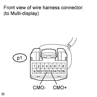
CHECK HARNESS AND CONNECTOR (NAVIGATION ECU - MULTI-DISPLAY)
-
Disconnect the navigation ECU connector and multi-display connector.
-
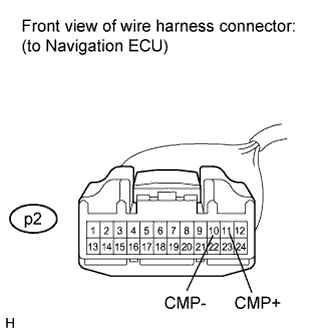
Measure the resistance according to the value(s) in the table below.
Standard Resistance Tester Connection Condition Specified Condition p1-12 (CMO-) - p2-10 (CMP-) Always Below 1 Ω p1-13 (CMO+) - p2-11 (CMP+) Always Below 1 Ω p1-12 (CMO-) - Body ground Always 10 kΩ or higher p1-13 (CMO+) - Body ground Always 10 kΩ or higher
NG
REPAIR OR REPLACE HARNESS OR CONNECTOR
OK 
PROCEED TO NEXT CIRCUIT INSPECTION SHOWN IN PROBLEM SYMPTOMS TABLE Click here
-