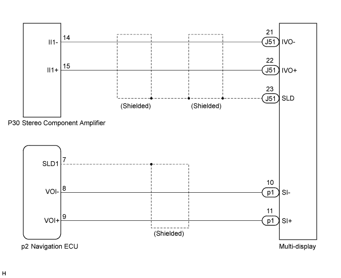
NAVIGATION SYSTEM Navigation Voice Circuit
DESCRIPTION
This circuit is used when the voice guidance in the navigation system is on.
WIRING DIAGRAM
INSPECTION PROCEDURE
PROCEDURE
-
CHECK HARNESS AND CONNECTOR (MULTI-DISPLAY - NAVIGATION ECU)
-
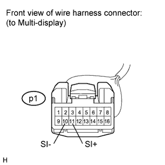
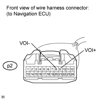
Disconnect the multi-display connector and the navigation ECU connector.
-
Measure the resistance according to the value(s) in the table below.
Standard Resistance Tester Connection Condition Specified Condition p2-8 (VOI-) - p1-10 (SI-) Always Below 1 Ω p2-9 (VOI+) - p1-11 (SI+) Always Below 1 Ω p2-8 (VOI-) - Body ground Always 10 kΩ or higher p2-9 (VOI+) - Body ground Always 10 kΩ or higher
NG 
REPAIR OR REPLACE HARNESS OR CONNECTOR
OK 
-
-
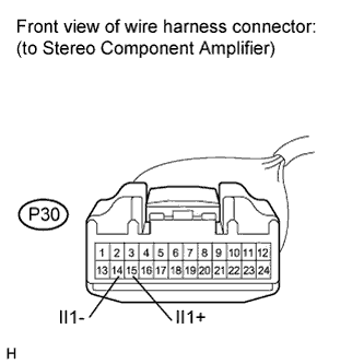
CHECK HARNESS AND CONNECTOR (MULTI-DISPLAY - STEREO COMPONENT AMPLIFIER)
-
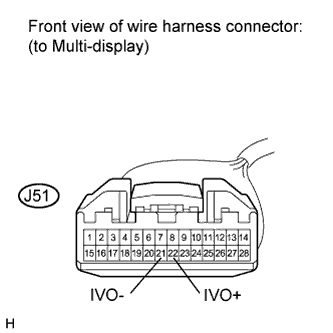
Disconnect the multi-display connector and stereo component amplifier connector.
-
Measure the resistance according to the value(s) in the table below.
Standard Resistance Tester Connection Condition Specified Condition J51-22 (IVO+) - P30-15 (II1+) Always Below 1 Ω J51-21 (IVO-) - P30-14 (II1-) Always Below 1 Ω J51-22 (IVO+) - Body ground Always 10 kΩ or higher J51-21 (IVO-) - Body ground Always 10 kΩ or higher
NG
REPAIR OR REPLACE HARNESS OR CONNECTOR
OK 
PROCEED TO NEXT CIRCUIT INSPECTION SHOWN IN PROBLEM SYMPTOMS TABLE Click here
-