NAVIGATION SYSTEM Reverse Signal Circuit
DESCRIPTION
The navigation ECU receives a reverse signal from the multi-display and information from the GPS antenna, and then adjusts vehicle position.
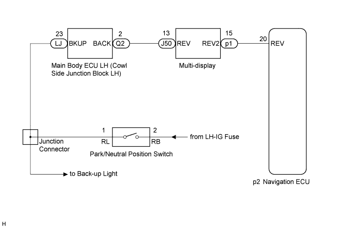
WIRING DIAGRAM
INSPECTION PROCEDURE
PROCEDURE
-
CHECK BACK-UP LIGHT
-
Move the shift lever to R and check if the back-up lights come on.
OK The back-up lights come on.
NG 
GO TO LIGHTING SYSTEM Click here
OK 
-
-
CHECK VEHICLE SIGNAL (DISPLAY CHECK MODE)
-
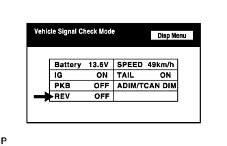
Enter the "Display Check" mode (Vehicle Signal Check Mode) Click here.
-
Check that the display changes between ON and OFF according to the shift lever operation (P and R).
OK Shift Lever Position Display Reverse ON Except Reverse OFF Tech Tips
This display is updated once per second. As a result, it is normal for the display to lag behind the actual change in the switch.
NG 
INSPECT MULTI-DISPLAY Click here
OK
-
-
CHECK HARNESS AND CONNECTOR (NAVIGATION ECU - MULTI-DISPLAY)
-
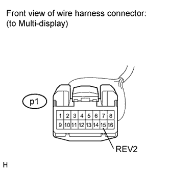
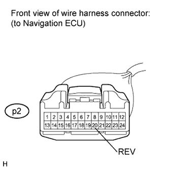
Disconnect the multi-display connector and navigation ECU connector.
-
Measure the resistance according to the value(s) in the table below.
Standard Resistance Tester Connection Condition Specified Condition p1-15 (REV2) - p2-20 (REV) Always Below 1 Ω p1-15 (REV2) - Body ground Always 10 kΩ or higher
NG
REPAIR OR REPLACE HARNESS OR CONNECTOR
OK
-
-
INSPECT NAVIGATION ECU
-
Reconnect the multi-display connector.
-
Measure the voltage according to the value(s) in the table below.
Standard Voltage Tester Connection Condition Specified Condition p2-20 (REV) - Body ground Engine switch on (IG).
Shift lever is moved to R.
11 to 14 V p2-20 (REV) - Body ground Engine switch on (IG).
Shift lever is moved to any position except R.
Below 1 V
NG
REPLACE MULTI-DISPLAY Click here
OK 
REPLACE NAVIGATION ECU Click here
-
-
INSPECT MULTI-DISPLAY
-
Disconnect the multi-display connector.
-
Measure the voltage according to the value(s) in the table below.
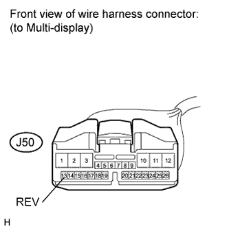
Standard Voltage Tester Connection Condition Specified Condition J50-13 (REV) - Body ground Engine switch on (IG).
Shift lever is moved to R.
11 to 14 V J50-13 (REV) - Body ground Engine switch on (IG).
Shift lever is moved to any position except R.
Below 1 V
NG
CHECK HARNESS AND CONNECTOR (MULTI-DISPLAY - MAIN BODY ECU LH) Click here
OK
REPLACE MULTI-DISPLAY Click here
-
-
CHECK HARNESS AND CONNECTOR (MULTI-DISPLAY - MAIN BODY ECU LH)
-
Disconnect the multi-display connector and main body ECU LH (cowl side junction block LH) connector.
-
Measure the resistance according to the value(s) in the table below.
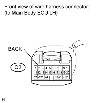
Standard Resistance Tester Connection Condition Specified Condition J50-13 (REV) - Q2-2 (BACK) Always Below 1 Ω J50-13 (REV) - Body ground Always 10 kΩ or higher
NG
REPAIR OR REPLACE HARNESS OR CONNECTOR
OK
-
-
CHECK HARNESS AND CONNECTOR (JUNCTION CONNECTOR - MAIN BODY ECU LH)
-
Disconnect the main body ECU LH (cowl side junction block LH) connector.
-
Measure the voltage according to the value(s) in the table below.
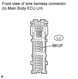
Standard Voltage Tester Connection Condition Specified Condition LJ-23 (BKUP) - Body ground Engine switch on (IG).
Shift lever is moved to R.
11 to 14 V LJ-23 (BKUP) - Body ground Engine switch on (IG).
Shift lever is moved to any position except R.
Below 1 V
NG
REPAIR OR REPLACE HARNESS OR CONNECTOR
OK
REPLACE MAIN BODY ECU LH
-