NAVIGATION SYSTEM Microphone Circuit between Overhead J/B and Multi-display
DESCRIPTION
This circuit sends a microphone signal from the overhead junction block to the multi-display. It also supplies power from the multi-display to the overhead junction block.
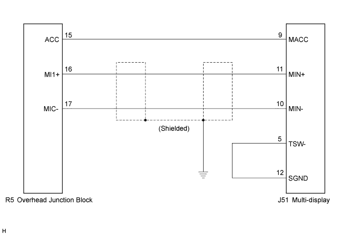
WIRING DIAGRAM
INSPECTION PROCEDURE
PROCEDURE
-
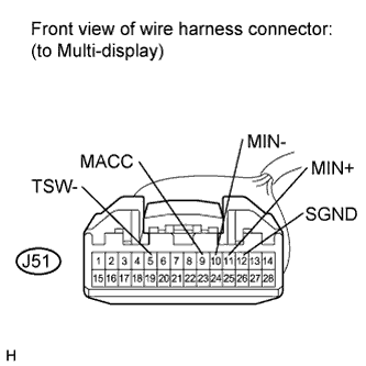
CHECK HARNESS AND CONNECTOR (OVERHEAD JUNCTION BLOCK - MULTI-DISPLAY)
-
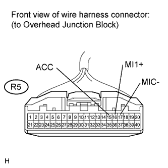
Disconnect the overhead junction block connector and multi-display connector.
-
Measure the resistance according to the value(s) in the table below.
Standard Resistance Tester Connection Condition Specified Condition R5-15 (ACC) - J51-9 (MACC) Always Below 1 Ω R5-16 (MI1+) - J51-11 (MIN+) Always Below 1 Ω R5-17 (MIC-) - J51-10 (MIN-) Always Below 1 Ω J51-5 (TSW-) - J51-12 (SGND) Always Below 1 Ω R5-15 (ACC) - Body ground Always 10 kΩ or higher R5-16 (MI1+) - Body ground Always 10 kΩ or higher R5-17 (MIC-) - Body ground Always 10 kΩ or higher
NG 
REPAIR OR REPLACE HARNESS OR CONNECTOR
OK 
-
-
INSPECT MULTI-DISPLAY
-
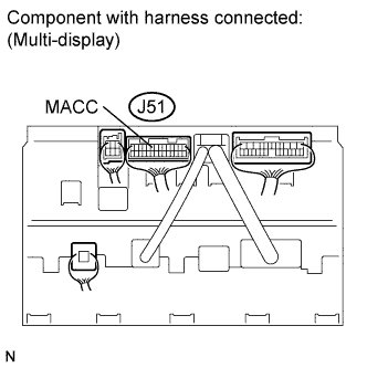
Reconnect the multi-display connector.
-
Measure the voltage according to the value(s) in the table below.
Standard Voltage Tester Connection Switch Condition Specified Condition J51-9 (MACC) - Body ground Engine switch on (ACC) 4 to 6 V
NG
REPLACE MULTI-DISPLAY Click here
OK 
PROCEED TO NEXT CIRCUIT INSPECTION SHOWN IN PROBLEM SYMPTOMS TABLE Click here
-