NAVIGATION SYSTEM, Diagnostic DTC:74-40

| DTC Code | DTC Name |
|---|---|
| 74-40 | Short in Speaker Circuit |
DESCRIPTION
| DTC No. | DTC Detection Condition | Trouble Area |
|---|---|---|
| 74-40 | A short is detected in the speaker output circuit. |
|
This circuit has a fail-safe function.
-
When a short in the speaker circuit is detected, all sound output is stopped.
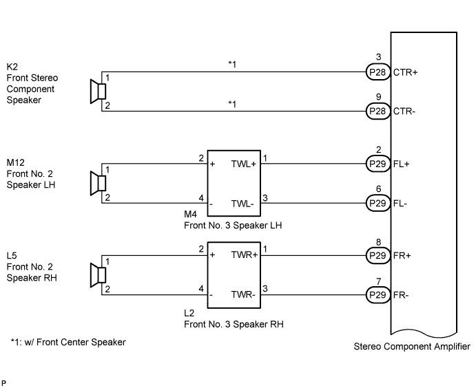
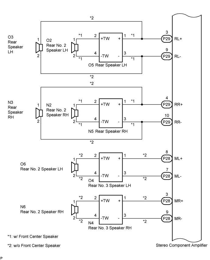
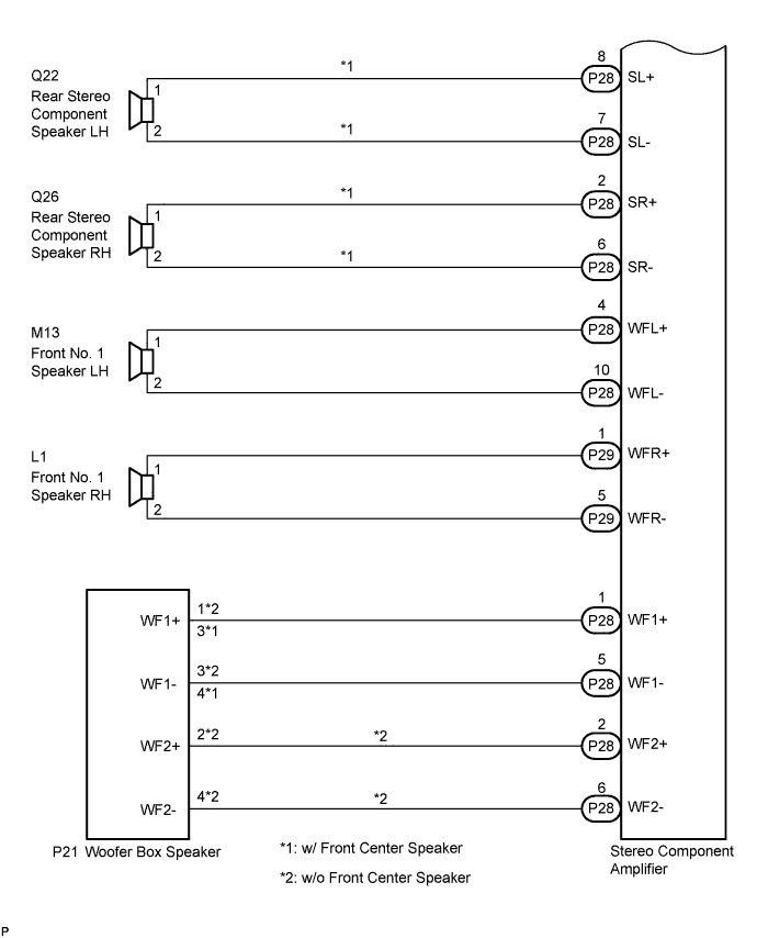
WIRING DIAGRAM
INSPECTION PROCEDURE
Tech Tips
After the inspection is completed, clear the DTCs.
PROCEDURE
-
INSPECT STEREO COMPONENT AMPLIFIER
-
Disconnect the stereo component amplifier connectors P29 and P28.
-
Clear the DTCs and recheck for DTCs.
-
Check if DTC 74-40 is output.
OK DTC 74-40 is not output.
NG 
REPLACE STEREO COMPONENT AMPLIFIER Click here
OK 
-
-
CHECK OPERATION
-
Reconnect the stereo component amplifier connector P29.
-
Check if DTC 74-40 is output.
OK DTC 74-40 is not output.
NG 
CHECK HARNESS AND CONNECTOR Click here
OK
-
-
CHECK HARNESS AND CONNECTOR
-
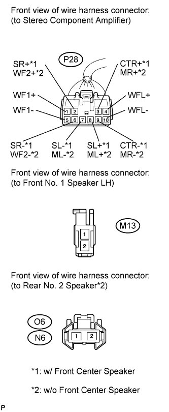
Disconnect the connectors shown in the illustration from the stereo component amplifier and speakers.
-
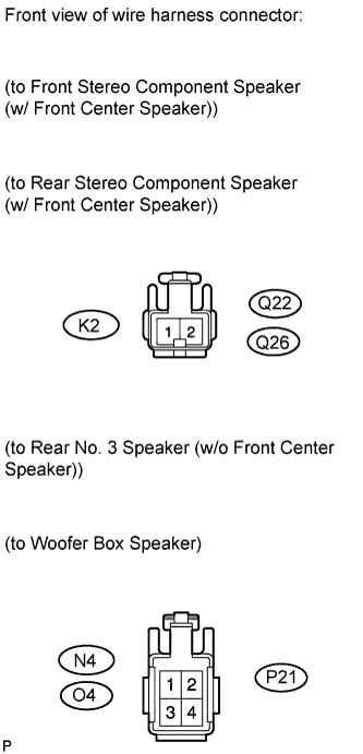
Measure the resistance according to the value(s) in the table below.
Standard Resistance Tester Connection Condition Specified Condition P28-3 (CTR+) - Body ground*1 Always 10 kΩ or higher P28-9 (CTR-) - Body ground*1 Always 10 kΩ or higher P28-8 (ML+) - Body ground*2 Always 10 kΩ or higher P28-7 (ML-) - Body ground*2 Always 10 kΩ or higher O4-2 (+TW) - Body ground*2 Always 10 kΩ or higher O4-4 (-TW) - Body ground*2 Always 10 kΩ or higher P28-3 (MR+) - Body ground*2 Always 10 kΩ or higher P28-9 (MR-) - Body ground*2 Always 10 kΩ or higher N4-2 (+TW) - Body ground*2 Always 10 kΩ or higher N4-4 (-TW) - Body ground*2 Always 10 kΩ or higher P28-8 (SL+) - Body ground*1 Always 10 kΩ or higher P28-7 (SL-) - Body ground*1 Always 10 kΩ or higher P28-2 (SR+) - Body ground*1 Always 10 kΩ or higher P28-6 (SR-) - Body ground*1 Always 10 kΩ or higher P28-4 (WFL+) - Body ground Always 10 kΩ or higher P28-10 (WFL-) - Body ground Always 10 kΩ or higher P28-2 (WF2+) - Body ground*2 Always 10 kΩ or higher P28-6 (WF2-) - Body ground*2 Always 10 kΩ or higher P28-1 (WF1+) - Body ground Always 10 kΩ or higher P28-5 (WF1-) - Body ground Always 10 kΩ or higher *1: w/ Front Center Speaker
*2: w/o Front Center Speaker
NG
REPAIR OR REPLACE HARNESS OR CONNECTOR
OK
-
-
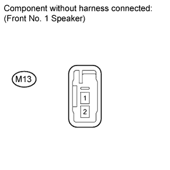
INSPECT FRONT NO. 1 SPEAKER (LEFT HAND)
-
Resistance check
-
Measure the resistance according to the value(s) in the table below.
Standard Resistance w/ Front Center Speaker Tester Connection Condition Specified Condition M13-1 - M13-2 Always 6 to 10 Ω w/o Front Center Speaker Tester Connection Condition Specified Condition M13-1 - M13-2 Always 3.2 to 4.8 Ω
-
NG
REPLACE FRONT NO. 1 SPEAKER (LEFT HAND) Click here
OK
-
-
CONFIRM MODEL
Result Result Proceed to w/o Front Center Speaker A w/ Front Center Speaker B
B
INSPECT REAR STEREO COMPONENT SPEAKER (LEFT HAND) Click here
A
-
INSPECT REAR NO. 2 SPEAKER (RIGHT HAND)
-
Reconnect the stereo component amplifier connector and rear No. 2 speaker connector.
-
Check that sound from the audio system can be heard from the speaker.
OK Sound from the audio system can be heard.
NG
REPLACE REAR NO. 2 SPEAKER (RIGHT HAND) Click here
OK
-
-
INSPECT REAR NO. 2 SPEAKER (LEFT HAND)
-
Reconnect the stereo component amplifier connector and rear No. 2 speaker connector.
-
Check that sound from the audio system can be heard from the speaker.
OK Sound from the audio system can be heard.
NG
REPLACE REAR NO. 2 SPEAKER (LEFT HAND) Click here
OK
-
-
INSPECT REAR NO. 3 SPEAKER (RIGHT HAND)
-
Reconnect the stereo component amplifier connector and rear No. 3 speaker connector.
-
Check that sound from the audio system can be heard from the speaker.
OK Sound from the audio system can be heard.
NG
REPLACE REAR NO. 3 SPEAKER (RIGHT HAND) Click here
OK
-
-
INSPECT REAR NO. 3 SPEAKER (LEFT HAND)
-
Reconnect the stereo component amplifier connector and rear No. 3 speaker connector.
-
Check that sound from the audio system can be heard from the speaker.
OK Sound from the audio system can be heard.
NG
REPLACE REAR NO. 3 SPEAKER (LEFT HAND) Click here
OK 
REPLACE WOOFER BOX SPEAKER Click here
-
-
INSPECT REAR STEREO COMPONENT SPEAKER (LEFT HAND)
-
Reconnect the stereo component amplifier connector and rear stereo component speaker connector.
-
Check that sound from the audio system can be heard from the speaker.
OK Sound from the audio system can be heard.
NG
REPLACE REAR STEREO COMPONENT SPEAKER (LEFT HAND) Click here
OK
-
-
INSPECT REAR STEREO COMPONENT SPEAKER (RIGHT HAND)
-
Reconnect the stereo component amplifier connector and rear stereo component speaker connector.
-
Check that sound from the audio system can be heard from the speaker.
OK Sound from the audio system can be heard.
NG
REPLACE REAR STEREO COMPONENT SPEAKER (RIGHT HAND) Click here
OK
-
-
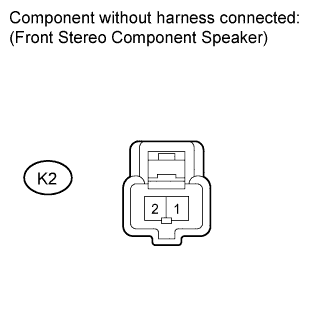
INSPECT FRONT STEREO COMPONENT SPEAKER
-
Resistance check
-
Measure the resistance according to the value(s) in the table below.
Standard Resistance Tester Connection Condition Specified Condition K2-1 - K2-2 Always 7 to 9 Ω
-
NG
REPLACE FRONT STEREO COMPONENT SPEAKER Click here
OK
REPLACE WOOFER BOX SPEAKER Click here
-
-
CHECK HARNESS AND CONNECTOR
-
Disconnect the connectors shown in the illustration from the stereo component amplifier and speakers.
-
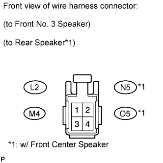
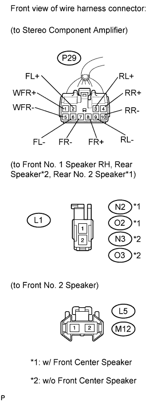
Measure the resistance according to the value(s) in the table below.
Standard Resistance Tester Connection Condition Specified Condition P29-2 (FL+) - Body ground Always 10 kΩ or higher P29-6 (FL-) - Body ground Always 10 kΩ or higher M4-2 (+) - Body ground Always 10 kΩ or higher M4-4 (-) - Body ground Always 10 kΩ or higher P29-8 (FR+) - Body ground Always 10 kΩ or higher P29-7 (FR-) - Body ground Always 10 kΩ or higher L2-2 (+) - Body ground Always 10 kΩ or higher L2-4 (-) - Body ground Always 10 kΩ or higher P29-3 (RL+) - Body ground Always 10 kΩ or higher P29-9 (RL-) - Body ground Always 10 kΩ or higher O5-2 (+TW) - Body ground*1 Always 10 kΩ or higher O5-4 (-TW) - Body ground*1 Always 10 kΩ or higher P29-4 (RR+) - Body ground Always 10 kΩ or higher P29-10 (RR-) - Body ground Always 10 kΩ or higher N5-2 (+TW) - Body ground*1 Always 10 kΩ or higher N5-4 (-TW) - Body ground*1 Always 10 kΩ or higher P29-1 (WFR+) - Body ground Always 10 kΩ or higher P29-5 (WFR-) - Body ground Always 10 kΩ or higher *1: w/ Front Center Speaker
NG
REPAIR OR REPLACE HARNESS OR CONNECTOR
OK
-
-
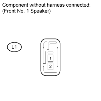
INSPECT FRONT NO. 1 SPEAKER (RIGHT HAND)
-
Resistance check
-
Measure the resistance according to the value(s) in the table below.
Standard Resistance w/ Front Center Speaker Tester Connection Condition Specified Condition L1-1 - L1-2 Always 6 to 10 Ω w/o Front Center Speaker Tester Connection Condition Specified Condition L1-1 - L1-2 Always 3.2 to 4.8 Ω
-
NG
REPLACE FRONT NO. 1 SPEAKER (RIGHT HAND) Click here
OK
-
-
INSPECT FRONT NO. 2 SPEAKER (RIGHT HAND)
-
Reconnect the stereo component amplifier connector and front No. 2 speaker connector.
-
Check that audio sound can be heard from the speaker.
OK Audio sound can be heard.
NG
REPLACE FRONT NO. 2 SPEAKER (RIGHT HAND) Click here
OK
-
-
INSPECT FRONT NO. 2 SPEAKER (LEFT HAND)
-
Reconnect the stereo component amplifier connector and front No. 2 speaker connector.
-
Check that audio sound can be heard from the speaker.
OK Audio sound can be heard.
NG
REPLACE FRONT NO. 2 SPEAKER (LEFT HAND) Click here
OK
-
-
INSPECT FRONT NO. 3 SPEAKER (RIGHT HAND)
-
Reconnect the stereo component amplifier connector and front No. 3 speaker connector.
-
Check that audio sound can be heard from the speaker.
OK Audio sound can be heard.
NG
REPLACE FRONT NO. 3 SPEAKER (RIGHT HAND) Click here
OK
-
-
INSPECT FRONT NO. 3 SPEAKER (LEFT HAND)
-
Reconnect the stereo component amplifier connector and front No. 3 speaker connector.
-
Check that audio sound can be heard from the speaker.
OK Audio sound can be heard.
NG
REPLACE FRONT NO. 3 SPEAKER (LEFT HAND) Click here
OK
-
-
CONFIRM MODEL
Result Result Proceed to w/ Front Center Speaker A w/o Front Center Speaker B
B
INSPECT REAR SPEAKER (LEFT HAND) Click here
A
-
INSPECT REAR NO. 2 SPEAKER (RIGHT HAND)
-
Reconnect the stereo component amplifier connector and rear No. 2 speaker connector.
-
Check that audio sound can be heard from the speaker.
OK Audio sound can be heard.
NG
REPLACE REAR NO. 2 SPEAKER (RIGHT HAND) Click here
OK
-
-
INSPECT REAR NO. 2 SPEAKER (LEFT HAND)
-
Reconnect the stereo component amplifier connector and rear No. 2 speaker connector.
-
Check that audio sound can be heard from the speaker.
OK Audio sound can be heard.
NG
REPLACE REAR NO. 2 SPEAKER (LEFT HAND) Click here
OK
-
-
INSPECT REAR SPEAKER (RIGHT HAND)
-
Reconnect the stereo component amplifier connector and rear speaker connector.
-
Check that audio sound can be heard from the speaker.
OK Audio sound can be heard.
NG
REPLACE REAR SPEAKER (RIGHT HAND) Click here
OK
REPLACE REAR SPEAKER (LEFT HAND) Click here
-
-
INSPECT REAR SPEAKER (LEFT HAND)
-
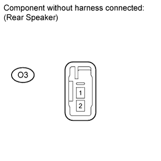
Resistance check
-
Measure the resistance according to the value(s) in the table below.
Standard Resistance Tester Connection Condition Specified Condition O3-1 - O3-2 Always 3.2 to 4.8 Ω
-
NG
REPLACE REAR SPEAKER (LEFT HAND) Click here
OK
REPLACE REAR SPEAKER (RIGHT HAND) Click here
-