AUDIO AND VISUAL SYSTEM (w/o Navigation System) Gateway ECU Power Source Circuit
DESCRIPTION
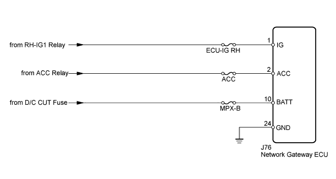
This is the power source circuit to operate the network gateway ECU.
WIRING DIAGRAM
INSPECTION PROCEDURE
PROCEDURE
-
INSPECT NETWORK GATEWAY ECU
-
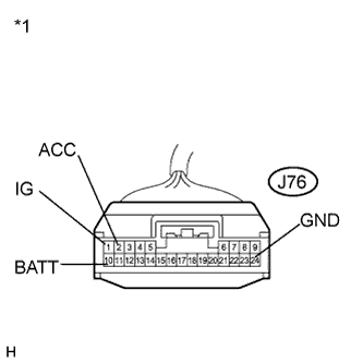
Text in Illustration *1 Front view of wire harness connector
(to Network Gateway ECU)
Disconnect the network gateway ECU connector.
-
Measure the resistance according to the value(s) in the table below.
Standard Resistance Tester Connection Condition Specified Condition J76-24 (GND) - Body ground Always Below 1 Ω -
Measure the voltage according to the value(s) in the table below.
Standard Voltage Tester Connection Condition Specified Condition J76-10 (BATT) - J76-24 (GND) Always 11 to 14 V J76-2 (ACC) - J76-24 (GND) Engine switch on (ACC) 11 to 14 V J76-1 (IG) - J76-24 (GND) Engine switch on (IG) 11 to 14 V
NG 
REPAIR OR REPLACE HARNESS OR CONNECTOR
OK 
PROCEED TO NEXT SUSPECTED AREA SHOWN IN PROBLEM SYMPTOMS TABLE Click here
-