AUDIO AND VISUAL SYSTEM (w/o Navigation System) Microphone Circuit between Microphone and Radio Receiver
DESCRIPTION
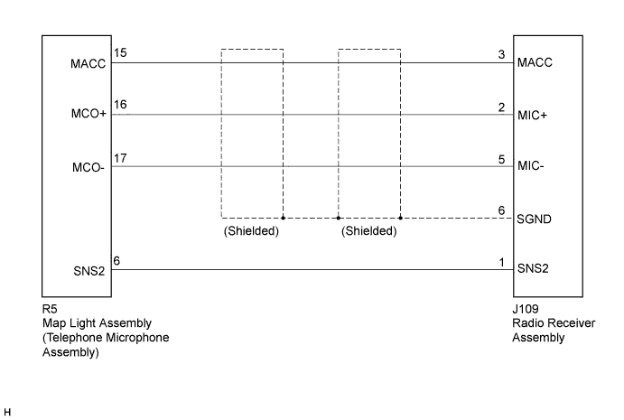
This circuit sends the microphone signal from the map light assembly (telephone microphone assembly) to the radio receiver assembly.
It also supplies power source from the radio receiver assembly to the map light assembly (telephone microphone assembly).
WIRING DIAGRAM
INSPECTION PROCEDURE
PROCEDURE
-
CHECK HARNESS AND CONNECTOR
-
Disconnect the radio receiver assembly and map light assembly connectors.
-
Measure the resistance according to the value(s) in the table below.
Standard Resistance Tester Connection Condition Specified Condition J109-1 (SNS2) - R5-6 (SNS2) Always Below 1 Ω J109-3 (MACC) - R5-15 (MACC) Always Below 1 Ω J109-2 (MIC+) - R5-16 (MCO+) Always Below 1 Ω J109-5 (MIC-) - R5-17 (MCO-) Always Below 1 Ω J109-1 (SNS2) - Body ground Always 10 kΩ or higher J109-3 (MACC) - Body ground Always 10 kΩ or higher J109-2 (MIC+) - Body ground Always 10 kΩ or higher J109-5 (MIC-) - Body ground Always 10 kΩ or higher J109-6 (SGND) - Body ground Always 10 kΩ or higher
NG 
REPAIR OR REPLACE HARNESS OR CONNECTOR
OK 
-
-
INSPECT RADIO RECEIVER ASSEMBLY
-
Disconnect the map light assembly connector.
-
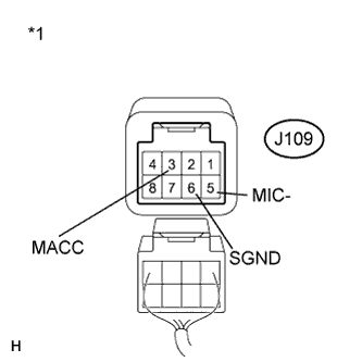
Text in Illustration *1 Component with harness connected
(Radio Receiver Assembly)
Reconnect the radio receiver assembly connector.
-
Measure the voltage according to the value(s) in the table below.
Standard Voltage Tester Connection Condition Specified Condition J109-3 (MACC) - Body ground Engine switch on (ACC) 4 to 6 V -
Measure the resistance according to the value(s) in the table below.
Standard Resistance Tester Connection Condition Specified Condition J109-6 (SGND) - Body ground Always Below 1 Ω J109-5 (MIC-) - Body ground Always Below 1 Ω
NG
REPLACE RADIO RECEIVER ASSEMBLY Click here
OK
-
-
INSPECT MAP LIGHT ASSEMBLY
-
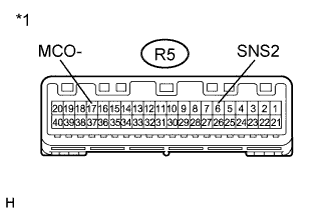
Text in Illustration *1 Component without harness connected
(Map Light Assembly)
Measure the resistance according to the value(s) in the table below.
Standard Resistance Tester Connection Condition Specified Condition R5-17 (MCO-) - R5-6 (SNS2) Always Below 1 Ω
NG 
REPLACE TELEPHONE MICROPHONE ASSEMBLY Click here
OK 
PROCEED TO NEXT SUSPECTED AREA SHOWN IN PROBLEM SYMPTOMS TABLE Click here
-
-
REPLACE TELEPHONE MICROPHONE ASSEMBLY
-
Replace the telephone microphone assembly Click here.
Note
The connector of the telephone microphone assembly is too small to be inspected. Therefore, after replacing the telephone microphone assembly, inspect it using the connector of the map light assembly.
-
Text in Illustration *1 Component without harness connected
(Map Light Assembly)
Measure the resistance according to the value(s) in the table below.
Standard Resistance Tester Connection Condition Specified Condition R5-6 (SNS2) - R5-17 (MCO-) Always Below 1 Ω
NG
REPLACE MAP LIGHT ASSEMBLY Click here
OK
PROCEED TO NEXT SUSPECTED AREA SHOWN IN PROBLEM SYMPTOMS TABLE Click here
-