- Click here
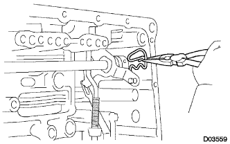
REMOVE PARK/NEUTRAL POSITION SWITCH ASSEMBLY
-
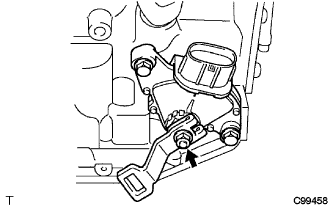
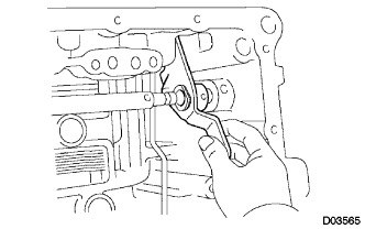
Remove the nut, washer and the control shaft lever.
-
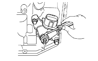
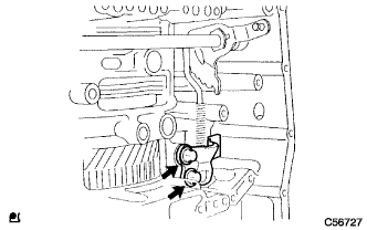
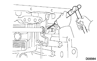
Using a screwdriver, pry up the lock plate.
-
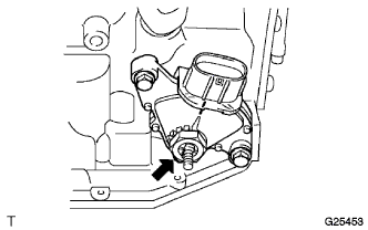
Remove the lock nut and the lock plate.
-
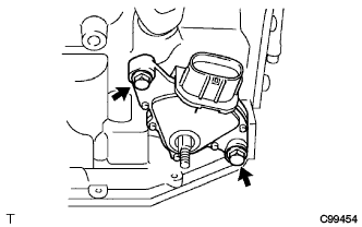
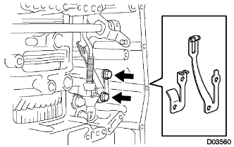
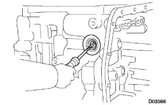
Remove the 2 bolts and pull out the park/neutral position switch.
-
- Click here
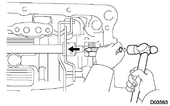
REMOVE BREATHER PLUG HOSE
-
Remove the breather plug hose from the transaxle case.
-
- Click here
REMOVE OIL COOLER TUBE UNION (INLET OIL COOLER UNION)
-
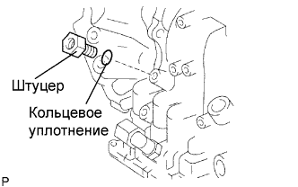
Remove the union.
-
Remove the O-ring from the union.
-
- Click here
REMOVE OIL COOLER TUBE UNION (OUTLET OIL COOLER UNION)
-
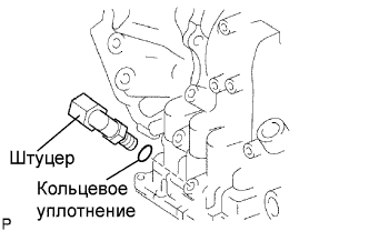
Remove the union.
-
Remove the O-ring from the union.
-
- Click here
REMOVE SPEED SENSOR
-
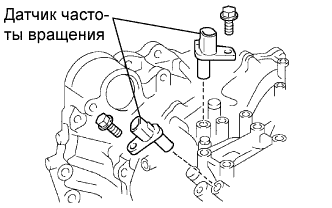
Remove the 2 bolts and the 2 speed sensors from the transaxle assembly.
-
- Click here
REMOVE NO. 1 TRANSAXLE CASE PLUG
-
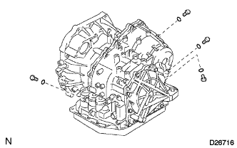
Remove the 4 No. 1 transaxle case plugs from the transaxle case.
-
Remove the 4 O-rings from the 4 No. 1 transaxle case plugs.
-
- Click here
SUPPORT AUTOMATIC TRANSAXLE ASSEMBLY
-
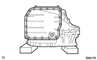
Support the transaxle assembly on wooden blocks.
-
- Click here
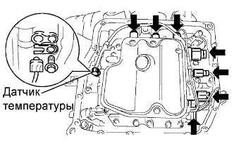
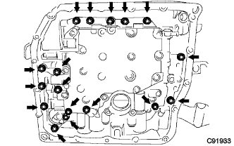
REMOVE AUTOMATIC TRANSAXLE OIL PAN SUB-ASSEMBLY
-
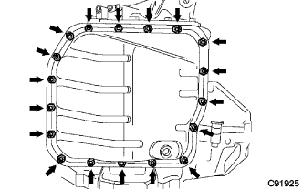
Remove the 18 bolts, oil pan, and gasket.
-
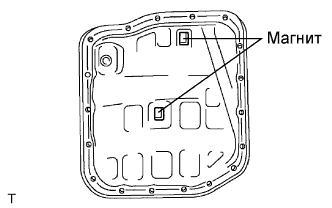
Remove the 2 magnets from the oil pan.
-
- Click here
INSPECT TRANSMISSION OIL CLEANER MAGNET
-
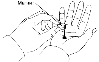
Remove the magnets and use them to collect any steel chips. Examine the chips and particles in the pan and on the magnet to determine what type of wear has occurred in the transaxle:
Result Steel (magnetic) Wear of the bearing, gear, and plate Brass (non-magnetic) Wear of the bushing
-
- Click here
DISCONNECT TRANSMISSION WIRE
-
Remove the 7 connectors from the shift solenoid valves.
-
Remove the bolt, lock plate, and temperature sensor.
-
- Click here
REMOVE TRANSMISSION WIRE
-
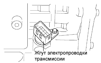
Remove the bolt and transmission wire from the transaxle case.
-
- Click here
REMOVE VALVE BODY OIL STRAINER ASSEMBLY
-
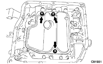
Remove the 3 bolts and oil strainer.
-
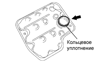
Remove the O-ring from the oil strainer.
-
- Click here
REMOVE TRANSMISSION VALVE BODY ASSEMBLY
-
Support the valve body assembly and remove the 17 bolts and valve body assembly.
-
- Click here
REMOVE NO. 1 GOVERNOR APPLY GASKET
-
Remove the No. 1 governor apply gasket from the transaxle case.
-
- Click here
REMOVE TRANSAXLE CASE 2ND BRAKE GASKET
-
Remove the transaxle case 2nd brake gasket from the transaxle case.
-
- Click here
REMOVE BRAKE DRUM GASKET
-
Remove the brake drum gasket from the transaxle case.
-
- Click here
REMOVE CHECK BALL BODY
-
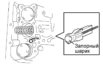
Remove the check ball body and spring from the transaxle case.
-
- Click here
REMOVE C-3 ACCUMULATOR PISTON
-
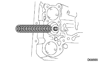
Remove the spring from the C-3 accumulator piston.
-
Apply compressed air (392 kPa, 4.0 kgf/cm2, 57 psi) to the oil hole and remove the C-3 accumulator piston.
Note:
-
Applying compressed air may cause the piston to jump-out. When removing the piston, hold it using a shop rag or a piece of cloth.
-
Take care not to splash ATF when applying compressed air.
-
-
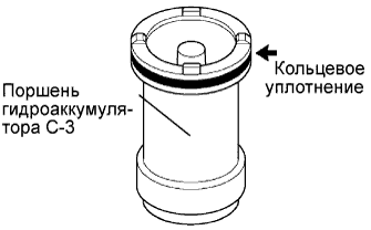
Remove the O-ring from the C-3 accumulator piston.
-
- Click here
REMOVE REVERSE CLUTCH ACCUMULATOR PISTON
-
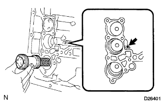
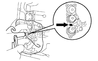
Apply compressed air (392 kPa, 4.0 kgf/cm2, 57 psi) to the oil hole and remove the reverse accumulator piston and spring.
Note:
-
Applying compressed air may cause the piston to jump-out. When removing the piston, hold it using a shop rag or a piece of cloth.
-
Take care not to splash ATF when applying compressed air.
-
-
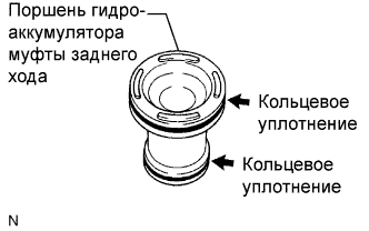
Remove the 2 O-rings from the reverse clutch accumulator piston.
-
- Click here
REMOVE B-3 ACCUMULATOR PISTON
-
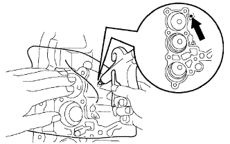
Apply compressed air (392 kPa, 4.0 kgf/cm2, 57 psi) to the oil hole and remove the B-3 accumulator piston and 2 springs.
Note:
-
Applying compressed air may cause the piston to jump-out. When removing the piston, hold it using a shop rag or a piece of cloth.
-
Take care not to splash ATF when applying compressed air.
-
-
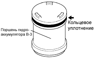
Remove the O-ring from the B-3 accumulator piston.
-
- Click here
REMOVE MANUAL VALVE LEVER SHAFT RETAINER SPRING
-
Using needle-nose pliers, remove the manual valve lever shaft retainer spring.
-
- Click here
REMOVE MANUAL DETENT SPRING SUB-ASSEMBLY
-
Remove the 2 bolts, the manual detent spring sub-assembly and cover.
-
- Click here
REMOVE PARKING LOCK PAWL BRACKET
-
Remove the 2 bolts and parking lock pawl bracket.
-
- Click here
REMOVE MANUAL VALVE LEVER SUB-ASSEMBLY
-
Using a chisel and hammer, cut off and remove the spacer.
-
Using a pin punch (φ35 mm) and hammer, drive out the pin.
Tip:Slowly drive out the pin so that it will not fall into the transaxle case.
-
Remove the manual valve lever shaft and manual valve lever.
-
- Click here
REMOVE PARKING LOCK ROD SUB-ASSEMBLY
-
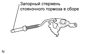
Remove the parking lock rod from the manual valve lever.
-
- Click here
REMOVE MANUAL VALVE LEVER SHAFT OIL SEAL
-
Using a screwdriver, remove the oil seal from the transaxle case.
Note:Do not apply excessive force when removing the oil seal.
-
- Click here
SUPPORT AUTOMATIC TRANSAXLE ASSEMBLY
-
Support the transaxle case with the oil pump side facing up.
-
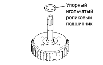
- Click here
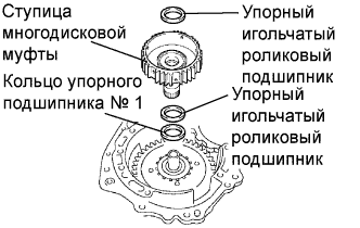
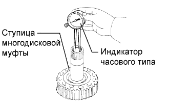
INSPECT INPUT SHAFT END PLAY
-
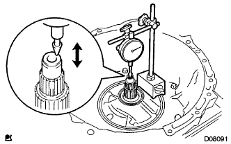
С помощью индикатора часового типа измерьте осевой люфт первичного вала.
Осевой люфт 0,262-1,244 мм (0,0103-0,0490 дюйма) Tip:Если результат не соответствует требованиям, замените первичный вал или упорный игольчатый роликовый подшипник.
-
- Click here
REMOVE TRANSAXLE HOUSING
-
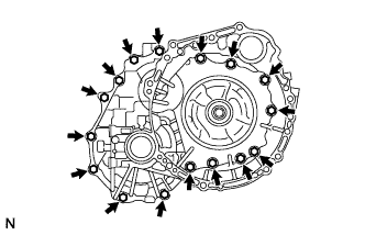
Remove the 16 bolts.
-
Tap on the circumference of the transaxle housing with a plastic hammer to remove the transaxle housing from the transaxle case.
Note:The differential may be accidentally removed when the transaxle housing is removed.
-
- Click here
REMOVE OIL PUMP ASSEMBLY
-
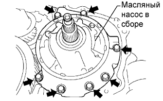
Remove the 7 bolts and oil pump from the transaxle case.
-
- Click here
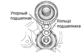
REMOVE THRUST NEEDLE ROLLER BEARING
-
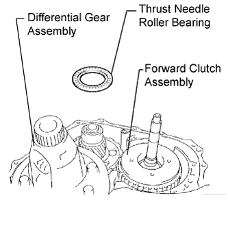
Remove the thrust needle roller bearing from the underdrive planetary gear assembly.
-
- Click here
REMOVE NO. 2 THRUST BEARING UNDERDRIVE RACE
-
Remove the No. 2 thrust bearing underdrive race from the underdrive planetary gear assembly.
-
- Click here
REMOVE DIFFERENTIAL GEAR ASSEMBLY
-
Remove the differential gear assembly from the transaxle case.
-
- Click here
REMOVE OVERDRIVE BRAKE GASKET
-
Remove the 2 overdrive brake gaskets from the transaxle case.
-
- Click here
REMOVE FORWARD CLUTCH ASSEMBLY
-
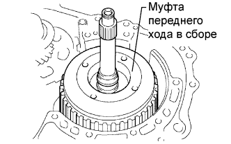
Remove the forward clutch assembly from the transaxle case.
-
Remove the thrust needle roller bearing from the forward clutch.
-
- Click here
REMOVE MULTIPLE DISC CLUTCH HUB
-
Remove the 2 thrust needle roller bearings, multiple disc clutch hub, and No. 1 thrust bearing race.
-
- Click here
INSPECT MULTIPLE DISC CLUTCH HUB
-
С помощью индикатора часового типа измерьте внутренний диаметр втулки ступицы муфты переднего хода.
Номинальный внутренний диаметр 23,025-23,046 мм (0,9065-0,9073 дюйма) Максимальный внутренний диаметр 23,09 мм (0,9091 дюйма) Note:
-
Проверьте контактную поверхность втулки вала муфты прямой передачи. При обнаружении царапин или обесцвечения замените муфту прямой передачи в сборе новой.
Если внутренний диаметр превышает максимально допустимый, замените ступицу муфты переднего хода новой.
-
-
- Click here
REMOVE UNDERDRIVE PLANETARY GEAR ASSEMBLY
-
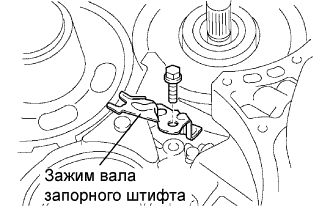
Remove the bolt and pawl shaft clamp.
-
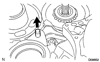
Remove the parking lock pawl shaft.
-
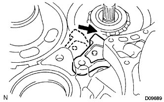
Push the parking lock pawl.
Tip:Failure to do this will cause interference when the underdrive planetary gear is removed.
-
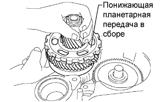
Remove the underdrive planetary gear assembly from the transaxle case.
Note:Be careful so that the underdrive planetary gear assembly will not fall off.
-
- Click here
REMOVE PARKING LOCK PAWL
-
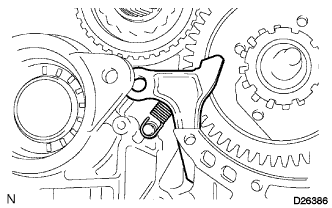
Remove the spring, pawl pin, and parking lock pawl.
-
- Click here
REMOVE UNDERDRIVE CLUTCH ASSEMBLY
-
Remove the underdrive clutch assembly, thrust bearing, and bearing race from the transaxle case.
-
- Click here
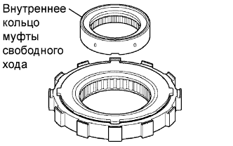
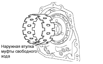
REMOVE UNDERDRIVE ONE-WAY CLUTCH ASSEMBLY
-
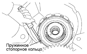
Using a screwdriver, remove the snap ring from the transaxle case.
Note:Do not apply excessive force when removing the snap ring.
-
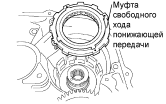
Remove the underdrive one-way clutch from the transaxle case.
-
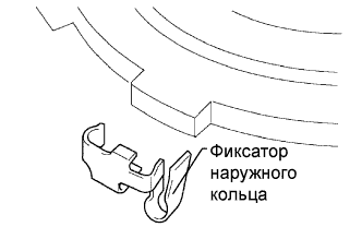
Remove the outer race retainer from the one-way clutch.
-
- Click here
REMOVE NO. 2 UNDERDRIVE CLUTCH DISC
-
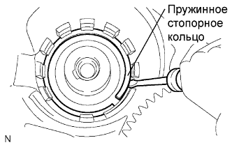
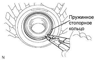
Using a screwdriver, remove the snap ring.
Note:Do not apply excessive force when removing the snap ring.
-
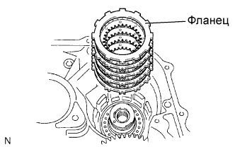
Remove the flange, 4 discs, and 4 plates from the transaxle case.
-
- Click here
INSPECT NO. 2 UNDERDRIVE CLUTCH DISC
-
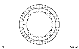
Убедитесь в отсутствии износа и подгорания поверхностей трения диска, пластины и фланца.
При необходимости замените их.
Note:
-
Если фрикционная накладка диска отслоилась или выцвела, или стерлась часть канавки, замените все диски.
-
Перед установкой новых дисков опустите их в трансмиссионную жидкость, как минимум, на 15 мин.
-
-
- Click here
REMOVE TRANSAXLE REAR COVER SUB-ASSEMBLY
-
Remove the 11 bolts.
-
Tap on the circumference of the rear cover with a plastic hammer to remove the transaxle rear cover from the transaxle case.
-
- Click here
REMOVE NO. 1 TRANSAXLE CASE PLUG
-
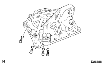
Remove the 4 No. 1 transaxle case plugs from the transaxle rear cover.
-
Remove the 4 No. 1 O-rings from the 4 transaxle case plugs.
-
- Click here
REMOVE REAR CLUTCH OIL SEAL RING OUTER
-
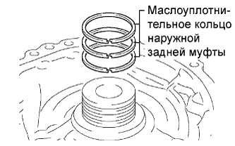
Remove the 3 rear clutch oil seal rings from the transaxle rear cover.
-
- Click here
REMOVE NEEDLE ROLLER BEARING
-
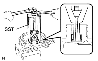
Using SST, remove the needle roller bearing from the transaxle rear cover.
09387-00041 09387-01021 09387-01030 09387-01040
-
- Click here
REMOVE NO. 1 GOVERNOR APPLY GASKET
-
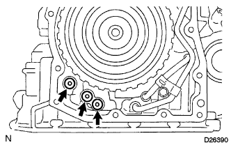
Using a screwdriver, remove the 3 apply gaskets.
-
- Click here
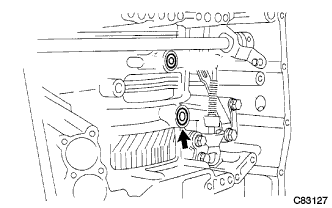
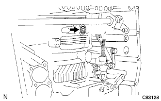
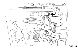
REMOVE BRAKE APPLY TUBE
-
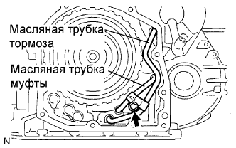
Remove the bolt, clamp, and brake apply tube.
-
Remove the clutch apply tube.
-
Remove the brake apply tube from the clamp.
Note:Do not bend the tubes.
-
- Click here
REMOVE DIRECT CLUTCH ASSEMBLY
-
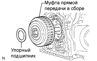
Remove the thrust bearing and the direct clutch assembly from the transaxle case.
-
- Click here
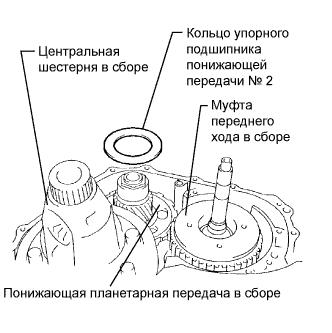
REMOVE OVERDRIVE DIRECT CLUTCH HUB SUB-ASSEMBLY
-
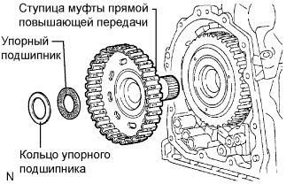
Remove the thrust bearing race, thrust bearing, and overdrive direct clutch hub from the planetary gear assembly.
-
- Click here
INSPECT OVERDRIVE DIRECT CLUTCH DRUM SUB-ASSEMBLY
-
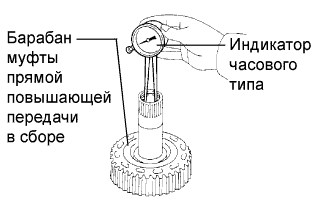
С помощью индикатора часового типа измерьте внутренний диаметр втулки ступицы муфты переднего хода.
Номинальный внутренний диаметр 23,025-23,046 мм (0,9065-0,9073 дюйма) Максимальный внутренний диаметр 23,09 мм (0,9091 дюйма) Note:
-
Проверьте контактную поверхность втулки вала муфты прямой передачи. При обнаружении царапин или обесцвечения замените муфту прямой передачи в сборе новой.
Если внутренний диаметр превышает максимально допустимый, замените ступицу муфты переднего хода новой.
-
-
- Click here
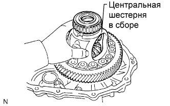
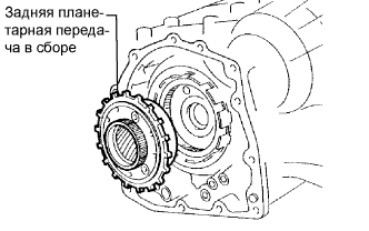
REMOVE REAR PLANETARY SUN GEAR ASSEMBLY
-
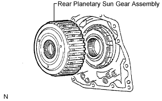
Remove the rear planetary sun gear assembly from the transaxle case.
-
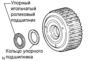
Remove the thrust needle roller bearing and thrust bearing race from the rear planetary sun gear assembly.
-
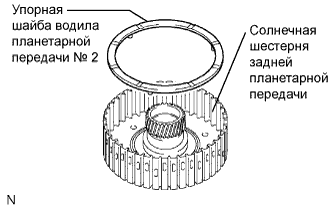
Remove the No. 2 planetary carrier thrust washer from the rear planetary sun gear assembly.
-
- Click here
REMOVE ONE-WAY CLUTCH ASSEMBLY
-
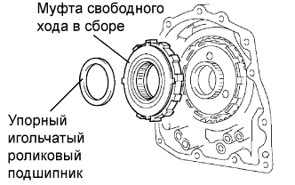
Remove the one-way clutch assembly and the thrust needle roller bearing from the transaxle case.
-
Remove the one-way clutch inner race from the one-way clutch assembly.
-
- Click here
REMOVE ONE-WAY CLUTCH SLEEVE OUTER
-
Remove the one-way clutch sleeve outer from the transaxle case.
-
- Click here
REMOVE NO. 1 PLANETARY CARRIER THRUST WASHER
-
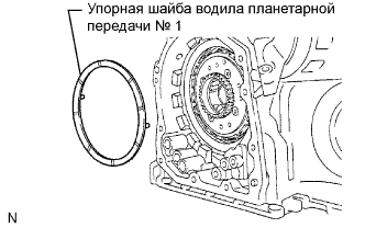
Remove the No. 1 planetary carrier thrust washer from the planetary gear assembly.
-
- Click here
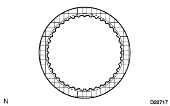
REMOVE 2ND BRAKE CLUTCH DISC
-
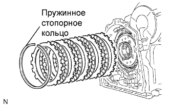
Using a screwdriver, remove the snap ring.
-
Remove the flange, 4 discs, and 4 plates from the transaxle case.
-
- Click here
INSPECT 2ND BRAKE CLUTCH DISC
-
Убедитесь в отсутствии износа и подгорания поверхностей трения диска, пластины и фланца.
При необходимости замените их.
Note:
-
Если фрикционная накладка диска отслоилась или выцвела, или стерлась часть канавки, замените все диски.
-
Перед установкой новых дисков опустите их в трансмиссионную жидкость, как минимум, на 15 мин.
-
-
- Click here
REMOVE 2ND BRAKE PISTON ASSEMBLY
-
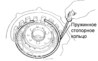
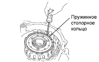
Using a screwdriver, remove the snap ring.
-
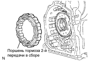
Remove the 2nd brake piston assembly from the transaxle case.
-
- Click here
REMOVE REAR PLANETARY GEAR ASSEMBLY
-
Using a screwdriver, remove the snap ring.
-
Remove the rear planetary gear assembly from the transaxle case.
-
- Click here
REMOVE INPUT SUN GEAR
-
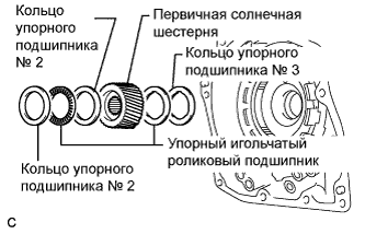
Remove the 2 thrust needle roller bearings, No. 2 thrust bearing race, No. 3 thrust bearing race, and the input sun gear from the transaxle case.
-
- Click here
REMOVE 1ST AND REVERSE BRAKE CLUTCH DISC
-
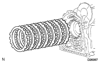
Remove the flange, 6 discs, and 6 plates from the transaxle case.
-
- Click here
INSPECT 1ST AND REVERSE BRAKE CLUTCH DISC
-
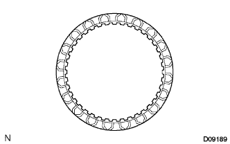
Убедитесь в отсутствии износа и подгорания поверхностей трения диска, пластины и фланца.
При необходимости замените их.
Note:
-
Если фрикционная накладка диска отслоилась или выцвела, или стерлась часть канавки, замените все диски.
-
Перед установкой новых дисков опустите их в трансмиссионную жидкость, как минимум, на 15 мин.
-
-
- Click here
REMOVE FRONT PLANETARY GEAR ASSEMBLY
-
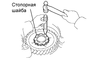
Using a chisel and hammer, unstake the lock washer.
Note:Push down all claws of the washer. Otherwise, SST cannot be fully pressed against the nut, and the nut cannot be loosened.
-
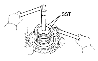
Using SST, remove the nut.
09387-00030 09387-00080 -
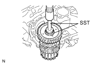
Using SST and a press, remove the front planetary gear assembly from the counter drive gear.
09950-60010 09951-00450 09950-70010 09951-07100 -
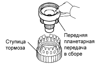
Remove the front planetary gear assembly from the brake hub.
-
- Click here
REMOVE FRONT PLANETARY RING GEAR
-
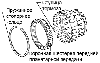
Using a screwdriver, remove the snap ring and front planetary ring gear from the brake hub.
-
- Click here
REMOVE 1ST AND REVERSE BRAKE RETURN SPRING SUB-ASSEMBLY
-
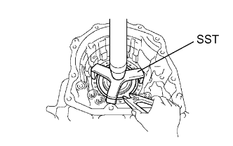
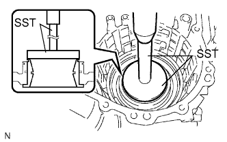
Place SST on the return spring, and compress the return spring with a press.
09387-00070 -
Using a snap ring expander, remove the snap ring.
Note:
-
Stop the press when the spring seat is lowered 1 to 2 mm (0.039 to 0.078 in.) from the snap ring groove to prevent the spring seat from being deformed.
-
Do not expand the snap ring excessively.
-
-
- Click here
INSPECT 1ST AND REVERSE BRAKE RETURN SPRING SUB-ASSEMBLY
-
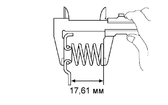
С помощью штангенциркуля измерьте длину пружины с седлом в свободном состоянии.
Номинальная длина в свободном состоянии 17,61 мм (0,6933 дюйма) Tip:Если результат не соответствует требованиям, замените пружину.
-
- Click here
REMOVE 1ST AND REVERSE BRAKE PISTON
-
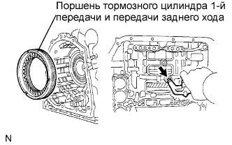
Apply compressed air (392 kPa, 4.0 kgf/cm2, 57 psi) to the transaxle case to remove the 1st and reverse brake piston.
Note:
-
Applying compressed air may cause the piston to jump-out. When removing the piston, hold it using a shop rag or a piece of cloth.
-
Take care not to splash ATF when applying compressed air.
-
-
Remove the 2 O-rings from the 1st and reverse brake piston.
-
- Click here
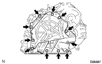
REMOVE COUNTER DRIVE GEAR
-
Using SST and a press, remove the counter drive gear from the transaxle case.
09950-60010 09951-00590 09950-70010 09951-07100 -
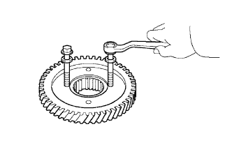
As shown in the illustration, tighten the 2 bolts evenly and make clearance of approx. 20.0 mm (0.787 in.) between the counter drive gear and the inner race.
-
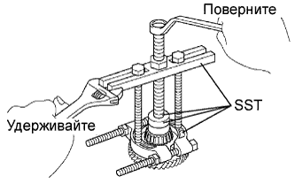
Using SST, remove the tapered roller bearing.
09950-60010 09951-00590 09950-00020 09950-00030 09950-40011 09957-04010
-
- Click here
REMOVE COUNTER DRIVE GEAR BEARING
-
Using a snap ring expander, remove the snap ring.
-
Using SST and a press, remove the bearing outer race.
09950-60020 09951-00910
-
- Click here
REMOVE NO. 2 BREATHER PLUG
- Click here
REMOVE UNDERDRIVE BRAKE RETURN SPRING SUB-ASSEMBLY
-
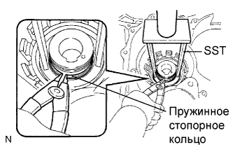
Place SST on the return spring, and compress the return spring with a press.
09387-00020 -
Using a snap ring expander, remove the snap ring.
Note:
-
Stop the press when the spring seat is lowered 1 to 2 mm (0.039 to 0.078 in.) from the snap ring groove, to prevent the spring seat from being deformed.
-
Do not expand the snap ring excessively.
-
-
- Click here
INSPECT UNDERDRIVE BRAKE RETURN SPRING SUB-ASSEMBLY
-
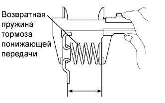
С помощью штангенциркуля измерьте длину пружины с седлом в свободном состоянии.
Номинальная длина в свободном состоянии 13,24 мм (0,5213 дюйма) Tip:Если результат не соответствует требованиям, замените пружину.
-
- Click here
REMOVE UNDERDRIVE BRAKE PISTON
-
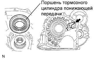
Apply compressed air (392 kPa, 4.0 kgf/cm2, 57 psi) to the transaxle case to remove the underdrive brake piston.
-
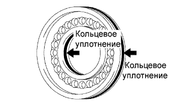
Remove the 2 O-rings from the underdrive brake piston.
-
- Click here
REMOVE NEEDLE ROLLER BEARING
-
Using SST, remove the needle roller bearing from the transaxle case.
09387-00041 09387-01010 09387-01030 09387-01040
-
- Click here
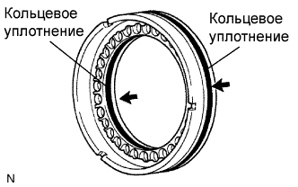
REMOVE UNDERDRIVE CLUTCH DRUM OIL SEAL RING
-
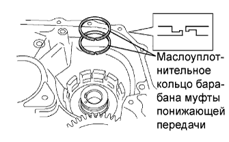
Remove the 2 oil seal rings from the transaxle case.
-
- Click here
REMOVE NO. 1 TRANSAXLE CASE PLUG
-
Remove the 2 No. 1 transaxle case plugs.
-
Remove the 2 O-rings from the 2 No. 1 transaxle case plugs.
-
- Click here
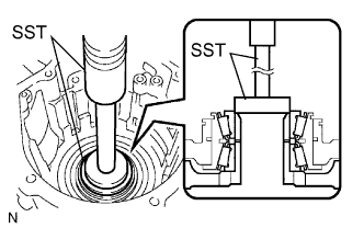
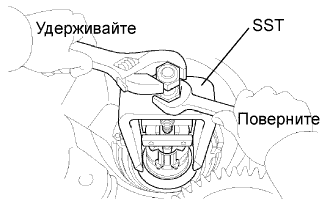
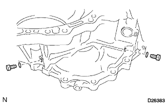
REMOVE UNDERDRIVE CYLINDRICAL ROLLER BEARING
-
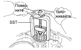
Using SST, remove the underdrive cylindrical roller bearing from the transaxle case.
09514-35011
-
- Click here
REMOVE UNDERDRIVE OUTPUT SHAFT OIL SEAL RING
-
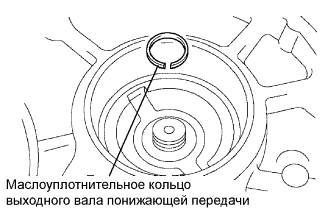
Remove the oil seal ring from the transaxle housing.
-
- Click here
REMOVE DIFFERENTIAL GEAR LUBE APPLY TUBE
-
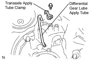
Remove the bolt, transaxle apply tube clamp and differential gear lube apply tube from the transaxle housing.
Note:Do not bend the tubes.
-