CAN COMMUNICATION SYSTEM, Diagnostic DTC:U1002 (CAN MS BUS)
| DTC Code | DTC Name |
|---|---|
| U1002 (CAN MS BUS) | Lost Communication with Gateway Module (Main body ECU) |
DESCRIPTION
-
The main body ECU will store this DTC when no signals can be received from the ECUs that have been memorized as those that are connected to the CAN MS bus.
-
When the main body ECU receives a response signal from the ECUs connected to the CAN MS bus, the main body ECU recognizes and memorizes that the ECU is connected to the CAN MS bus. Based on this memorized data, the main body ECU monitors for malfunctions in the ECUs connected to the CAN MS bus when communicating with those ECUs. If the main body ECU cannot receive response signals from the ECUs that have been memorized as those connected to the CAN MS bus, the main body ECU determines that a malfunction exists.
| DTC No. | DTC Detection Condition | Trouble Area |
|---|---|---|
| U1002 | Main body ECU cannot receive signals from all ECUs that have been memorized as those connected to the CAN MS bus. |
|
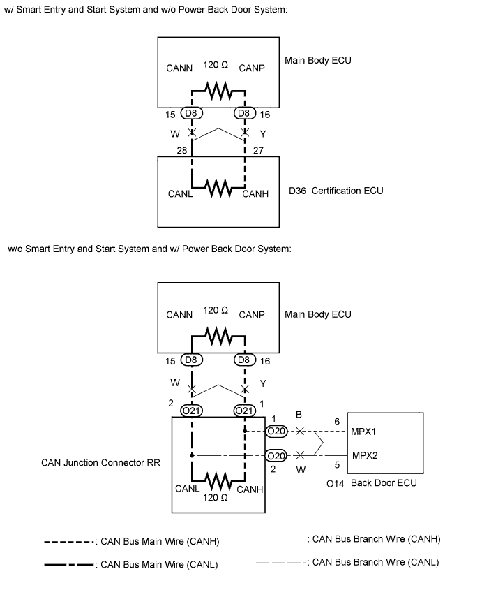
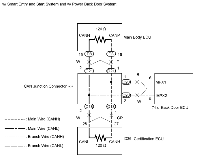
WIRING DIAGRAM
INSPECTION PROCEDURE
Note
-
Turn the ignition switch off before measuring the resistances of CAN bus main wires and CAN bus branch wires.
-
After the ignition switch is turned off, check that the key reminder warning system and light reminder warning system are not in operation.
-
Before measuring the resistance, leave the vehicle as is for at least 1 minute and do not operate the ignition switch, any other switches, or the doors. If any doors need to be opened in order to check connectors, open the doors and leave them open.
Tech Tips
-
Operating the ignition switch, any other switches, or a door triggers related ECU and sensor communication on the CAN. This communication will cause the resistance value to change.
-
Even after DTCs are cleared, if a DTC is stored again after driving the vehicle for a while, the malfunction may be occurring due to vibration of the vehicle. In such a case, wiggling the ECUs or wire harness while performing the inspection below will help determine the cause of the malfunction.
PROCEDURE
-
CHECK VEHICLE TYPE
Result Result Proceed to w/o Power back door A w/ Power back door B
B 
CHECK CAN MS BUS WIRE Click here
A 
-
CHECK CAN MS BUS WIRE
-
Turn the ignition switch off.
-
Disconnect the certification ECU connector.
-
Measure the resistance according to the value(s) in the table below.
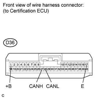
Standard resistance Tester Connection Condition Specified Condition Result D36-27 (CANH) - D36-28 (CANL) Ignition switch off 108 to 132 Ω Below 108 Ω: Short in line 133 Ω or more: Open in CAN main bus line D36-27 (CANH) - D36-17 (E) Ignition switch off 200 Ω or higher Below 200 Ω: Ground short D36-28 (CANL) - D36-17 (E) D36-27 (CANH) - D36-1 (+B) Negative battery terminal disconnected 6 kΩ or higher Below 6 kΩ: +B short D36-28 (CANL) - D36-1 (+B) Result Result Proceed to OK A Open in CAN main wire B Short in line, Ground short, +B short C
B
CHECK FOR OPEN IN CAN MS BUS MAIN WIRE Click here
C
CHECK FOR SHORT IN CAN MS BUS WIRES Click here
A
-
-
CHECK CAN MS BUS WIRE
-
Reconnect the certification ECU connector.
-
Disconnect the main body ECU connector.
-
Measure the resistance according to the value(s) in the table below.
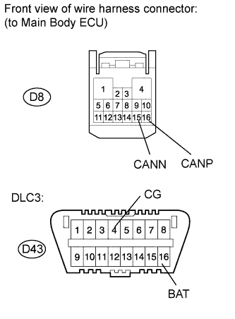
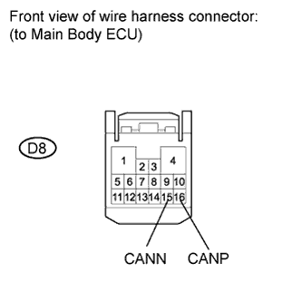
Standard resistance Tester Connection Condition Specified Condition D8-16 (CANP) - D8-15 (CANN) Ignition switch off 108 to 132 Ω D8-16 (CANP) - D43-4 (CG) Ignition switch off 200 Ω or higher D8-15 (CANN) - D43-4 (CG) D8-16 (CANP) - D43-16 (BAT) Negative battery terminal disconnected 6 kΩ or higher D8-15 (CANN) - D43-16 (BAT)
NG 
REPLACE CERTIFICATION ECU
OK 
REPLACE INSTRUMENT PANEL JUNCTION BLOCK ASSEMBLY (MAIN BODY ECU)
-
-
CHECK FOR OPEN IN CAN MS BUS MAIN WIRE
-
Reconnect the certification ECU connector.
-
Disconnect the main body ECU connector.
-
Measure the resistance according to the value(s) in the table below.
Standard resistance Tester Connection Condition Specified Condition D8-16 (CANP) - D8-15 (CANN) Ignition switch off 108 to 132 Ω
NG
REPAIR OR REPLACE CAN MS BUS MAIN WIRE OR CONNECTOR (MAIN BODY ECU - CERTIFICATION ECU)
OK
REPLACE INSTRUMENT PANEL JUNCTION BLOCK ASSEMBLY (MAIN BODY ECU)
-
-
CHECK FOR SHORT IN CAN MS BUS WIRES
-
Reconnect the certification ECU connector.
-
Disconnect the main body ECU connector (D8).
-
Measure the resistance according to the value(s) in the table below.
Standard resistance Tester Connection Condition Specified Condition D8-16 (CANP) - D8-15 (CANN) Ignition switch off 108 to 132 Ω D8-16 (CANP) - D43-4 (CG) Ignition switch off 200 Ω or higher D8-15 (CANN) - D43-4 (CG) D8-16 (CANP) - D43-16 (BAT) Negative battery terminal disconnected 6 kΩ or higher D8-15 (CANN) - D43-16 (BAT)
NG
REPAIR OR REPLACE CAN MS BUS MAIN WIRE OR CONNECTOR (MAIN BODY ECU - CERTIFICATION ECU)
OK
REPLACE INSTRUMENT PANEL JUNCTION BLOCK ASSEMBLY (MAIN BODY ECU)
-
-
CHECK CAN MS BUS WIRE
-
Turn the ignition switch off.
-
Measure the resistance according to the value(s) in the table below.
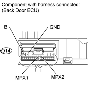
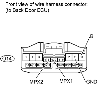
Standard resistance Tester Connection Condition Specified Condition Result O14-6 (MPX1) - O14-5 (MPX2) Ignition switch off 54 to 69 Ω Below 54 Ω: Short in line 70 Ω or more: Open in CAN main bus line O14-6 (MPX1) - O14-11 (GND) Ignition switch off 200 Ω or higher Below 200 Ω: Ground short O14-5 (MPX2) - O14-11 (GND) O14-6 (MPX1) - O14-12 (B) Negative battery terminal disconnected 6 kΩ or higher Below 6 kΩ: +B short O14-5 (MPX2) - O14-12 (B) Result Result Proceed to OK A Open in CAN main wire B Short in line, Ground short, +B short C
B
CHECK FOR OPEN IN CAN MS BUS MAIN WIRE Click here
C
CHECK FOR SHORT IN CAN MS BUS WIRES Click here
A
REPLACE INSTRUMENT PANEL JUNCTION BLOCK ASSEMBLY (MAIN BODY ECU)
-
-
CHECK FOR OPEN IN CAN MS BUS MAIN WIRE
-
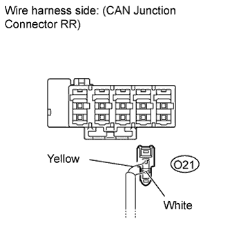
Disconnect the main body ECU junction connector from the CAN junction connector RR.
-
Measure the resistance according to the value(s) in the table below.
Standard resistance Tester Connection Condition Specified Condition O14-6 (MPX1) - O14-5 (MPX2) Ignition switch off 108 to 132 Ω Result Result Proceed to OK A NG (w/o Smart entry and start system) B NG (w/ Smart entry and start system) C
B
REPLACE CAN JUNCTION CONNECTOR RR
C
CHECK FOR OPEN IN CAN MS BUS MAIN WIRE Click here
A
-
-
CHECK FOR OPEN IN CAN MS BUS MAIN WIRE
-
Reconnect the main body ECU junction connector to the CAN junction connector RR.
-
Disconnect the main body ECU connector from the main body ECU.
-
Measure the resistance according to the value(s) in the table below.
Standard resistance Tester Connection Condition Specified Condition D8-16 (CANP) - D8-15 (CANN) Ignition switch off 108 to 132 Ω
NG
REPAIR OR REPLACE CAN MS BUS MAIN WIRE OR CONNECTOR (MAIN BODY ECU MAIN WIRE)
OK
REPLACE INSTRUMENT PANEL JUNCTION BLOCK ASSEMBLY (MAIN BODY ECU)
-
-
CHECK FOR OPEN IN CAN MS BUS MAIN WIRE
-
Reconnect the main body ECU junction connector to the CAN junction connector RR.
-
Disconnect the certification ECU connector from the certification ECU.
-
Measure the resistance according to the value(s) in the table below.
Standard resistance Tester Connection Condition Specified Condition D36-27 (CANH) - D36-28 (CANL) Ignition switch off 108 to 132 Ω
NG
REPAIR OR REPLACE CAN MS BUS MAIN WIRE OR CONNECTOR (CERTIFICATION ECU BRANCH WIRE)
OK
REPLACE CERTIFICATION ECU
-
-
CHECK FOR SHORT IN CAN MS BUS WIRES
-
Disconnect the back door ECU connector.
-
Measure the resistance according to the value(s) in the table below.
Standard resistance Tester Connection Condition Specified Condition O14-6 (MPX1) - O14-5 (MPX2) Ignition switch off 54 to 69 Ω O14-6 (MPX1) - O14-11 (GND) Ignition switch off 200 Ω or higher O14-5 (MPX2) - O14-11 (GND) O14-6 (MPX1) - O14-12 (B) Negative battery terminal disconnected 6 kΩ or higher O14-5 (MPX2) - O14-12 (B)
NG
CHECK FOR SHORT IN CAN MS BUS WIRES Click here
OK
REPLACE BACK DOOR MOTOR UNIT (BACK DOOR ECU) Click here
-
-
CHECK FOR SHORT IN CAN MS BUS WIRES
-
Disconnect the back door ECU junction connector from the CAN junction connector RR.
-
Measure the resistance according to the value(s) in the table below.
Standard resistance Tester Connection Condition Specified Condition O14-6 (MPX1) - O14-5 (MPX2) Ignition switch off 1 MΩ or higher O14-6 (MPX1) - O14-11 (GND) Ignition switch off 200 Ω or higher O14-5 (MPX2) - O14-11 (GND) O14-6 (MPX1) - O14-12 (B) Negative battery terminal disconnected 6 kΩ or higher O14-5 (MPX2) - O14-12 (B)
NG
REPAIR OR REPLACE CAN MS BUS BRANCH WIRE OR CONNECTOR (BACK DOOR ECU)
OK
-
-
CHECK FOR SHORT IN CAN MS BUS WIRES
-
Reconnect the back door ECU junction connector from the CAN junction connector RR.
-
Disconnect the main body ECU junction connector from the CAN junction connector RR.
-
Measure the resistance according to the value(s) in the table below.
Standard resistance Tester Connection Condition Specified Condition O14-6 (MPX1) - O14-5 (MPX2) Ignition switch off 108 to 132 Ω O14-6 (MPX1) - O14-11 (GND) Ignition switch off 200 Ω or higher O14-5 (MPX2) - O14-11 (GND) O14-6 (MPX1) - O14-12 (B) Negative battery terminal disconnected 6 kΩ or higher O14-5 (MPX2) - O14-12 (B) Result Result Proceed to OK A NG (w/o Smart entry and start system) B NG (w/ Smart entry and start system) C
B
REPLACE CAN JUNCTION CONNECTOR RR
C
CHECK FOR SHORT IN CAN MS BUS WIRES Click here
A
-
-
CHECK FOR SHORT IN CAN BUS MAIN WIRE
-
Reconnect the main body ECU junction connector to the CAN junction connector RR.
-
Disconnect the main body ECU connector from the main body ECU.
-
Measure the resistance according to the value(s) in the table below.
Standard resistance Tester Connection Condition Specified Condition D8-16 (CANP) - D8-15 (CANN) Ignition switch off 108 to 132 Ω D8-16 (CANP) - D43-4 (CG) Ignition switch off 200 Ω or higher D8-15 (CANN) - D43-4 (CG) D8-16 (CANP) - D43-16 (BAT) Negative battery terminal disconnected 6 kΩ or higher D8-15 (CANN) - D43-16 (BAT)
NG
REPAIR OR REPLACE CAN MS BUS MAIN WIRE OR CONNECTOR (MAIN BODY ECU MAIN WIRE)
OK
REPLACE INSTRUMENT PANEL JUNCTION BLOCK ASSEMBLY (MAIN BODY ECU)
-
-
CHECK FOR SHORT IN CAN MS BUS WIRES
-
Reconnect the main body ECU junction connector to the CAN junction connector RR.
-

Disconnect the certification ECU junction connector from the CAN junction connector RR.
-
Measure the resistance according to the value(s) in the table below.
Standard resistance Tester Connection Condition Specified Condition O14-6 (MPX1) - O14-5 (MPX2) Ignition switch off 108 to 132 Ω O14-6 (MPX1) - O14-11 (GND) Ignition switch off 200 Ω or higher O14-5 (MPX2) - O14-11 (GND) O14-6 (MPX1) - O14-12 (B) Negative battery terminal disconnected 6 kΩ or higher O14-5 (MPX2) - O14-12 (B)
NG
REPLACE CAN JUNCTION CONNECTOR RR
OK
-
-
CHECK FOR SHORT IN CAN MS BUS WIRES
-
Reconnect the certification ECU junction connector to the CAN junction connector RR.
-
Disconnect the certification ECU connector from the certification ECU.
-
Measure the resistance according to the value(s) in the table below.
Standard resistance Tester Connection Condition Specified Condition D36-27 (CANH) - D36-28 (CANL) Ignition switch off 108 to 132 Ω D36-27 (CANH) - D36-17 (E) Ignition switch off 200 Ω or higher D36-28 (CANL) - D36-17 (E) D36-27 (CANH) - D36-1 (+B) Negative battery terminal disconnected 6 kΩ or higher D36-28 (CANL) - D36-1 (+B)
NG
REPAIR OR REPLACE CAN MS BUS MAIN WIRE OR CONNECTOR (CERTIFICATION ECU BRANCH WIRE)
OK
REPLACE CERTIFICATION ECU
-