CAN COMMUNICATION SYSTEM TERMINALS OF ECU
Note
-
Turn the ignition switch off before measuring the resistances of CAN bus main wires and CAN bus branch wires.
-
After the ignition switch is turned off, check that the key reminder warning system and light remainder warning system are not operating.
-
Before measuring the resistance, leave the vehicle as is for at least 1 minute and do not operate the ignition switch, any other switches, or the doors. If any doors need to be opened in order to check the connectors, open the doors and leave them open.
Tech Tips
Operating the ignition switch, any other switches, or a door triggers related ECU and sensor communication on the CAN.
This communication will cause the resistance value to change.
Note
This section describes the standard CAN values for all CAN related components.
-
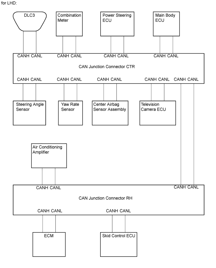
JUNCTION CONNECTOR FOR CAN BUS (for LHD)
-
CAN junction connector CTR
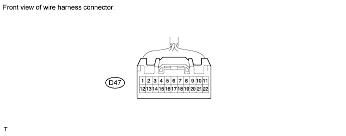
CAN Junction Connector CTR Wiring Color Connect to D47-1 (CANH) SB CAN junction connector RH D47-12 (CANL) W CAN junction connector RH D47-2 (CANH) V Yaw rate sensor D47-13 (CANL) W Yaw rate sensor D47-3 (CANH) Y Center airbag sensor assembly D47-14 (CANL) W Center airbag sensor assembly D47-4 (CANH) L DLC3 D47-15 (CANL) W DLC3 D47-5 (CANH) R Steering angle sensor D47-16 (CANL) W Steering angle sensor D47-6 (CANH) P Combination meter D47-17 (CANL) W Combination meter D47-7 (CANH) BR Power steering ECU D47-18 (CANL) W Power steering ECU D47-8 (CANH) GR Main body ECU D47-19 (CANL) W Main body ECU D47-9 (CANH) SB Television camera ECU D47-20 (CANL) W Television camera ECU -
CAN junction connector RH
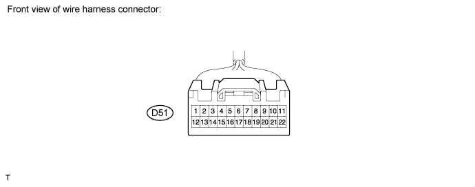
CAN Junction Connector RH Wiring Color Connect to D51-1 (CANH) R ECM D51-12 (CANL) W ECM D51-3 (CANH) LG Air conditioning amplifier D51-14 (CANL) W Air conditioning amplifier D51-4 (CANH) B Skid control ECU D51-15 (CANL) W Skid control ECU D51-5 (CANH) SB CAN junction connector CTR D51-16 (CANL) W CAN junction connector CTR -
The connection diagram of the components which are connected to the CAN junction connector.
-
-
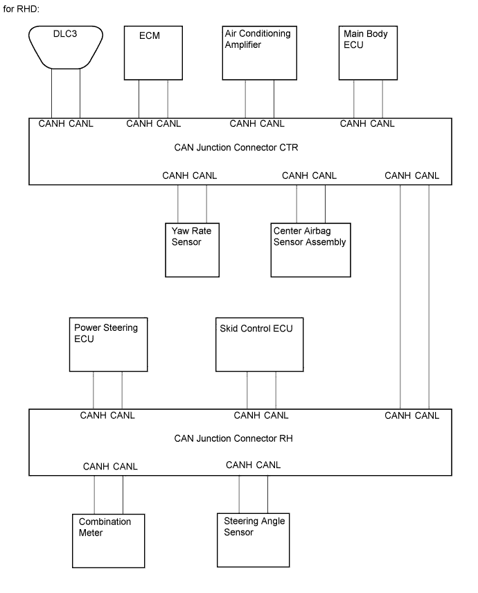
JUNCTION CONNECTOR FOR CAN BUS (for RHD)
-
CAN junction connector CTR
CAN Junction Connector CTR Wiring Color Connect to D47-1 (CANH) SB CAN junction connector RH D47-12 (CANL) W CAN junction connector RH D47-2 (CANH) G Yaw rate sensor D47-13 (CANL) W Yaw rate sensor D47-3 (CANH) Y Center airbag sensor assembly D47-14 (CANL) W Center airbag sensor assembly D47-4 (CANH) L DLC3 D47-15 (CANL) W DLC3 D47-5 (CANH) R ECM D47-16 (CANL) W ECM D47-6 (CANH) P Air conditioning amplifier D47-17 (CANL) W Air conditioning amplifier D47-8 (CANH) GR Main body ECU D47-19 (CANL) W Main body ECU -
CAN junction connector RH
CAN Junction Connector RH Wiring Color Connect to D51-1 (CANH) R Steering angle sensor D51-12 (CANL) W Steering angle sensor D51-2 (CANH) BR Power steering ECU D51-13 (CANL) W Power steering ECU D51-3 (CANH) P Combination meter D51-14 (CANL) W Combination meter D51-4 (CANH) B Skid control ECU D51-15 (CANL) W Skid control ECU D51-5 (CANH) SB CAN junction connector CTR D51-16 (CANL) W CAN junction connector CTR -
The connection diagram of the components which are connected to the CAN junction connector.
-
-
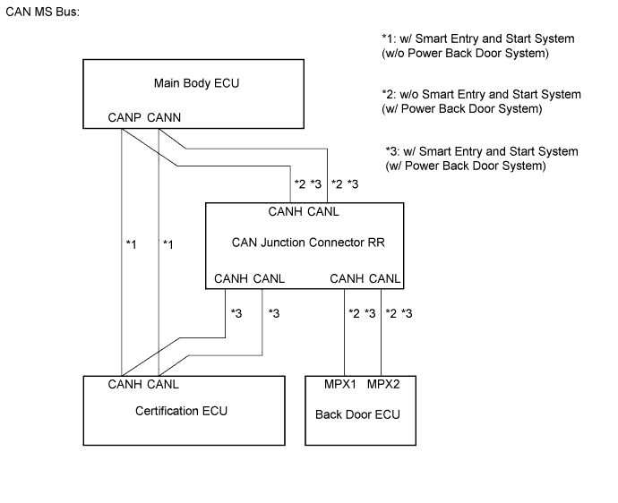
JUNCTION CONNECTOR FOR CAN MS BUS (w/ POWER BACK DOOR SYSTEM)
-
CAN junction connector RR
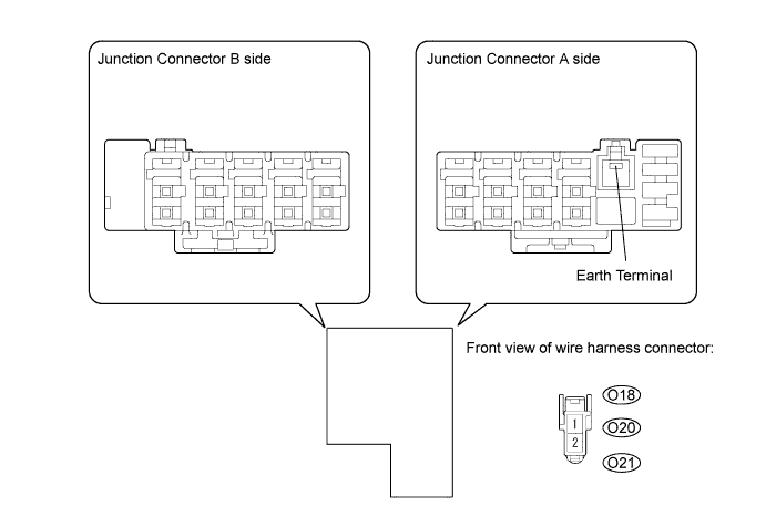
CAN Junction Connector RR Wiring Color Connect to O18-1 (CANH) B Back door ECU*2
O18-2 (CANL) W Back door ECU*2
O20-1 (CANH) GR Certification ECU*1
O20-2 (CANL) W Certification ECU*1
O21-1 (CANH) Y Main body ECU*2
O21-2 (CANL) W Main body ECU*2
Tech Tips
-
*1: w/ Smart entry and start system and power back door system.
-
*2: w/ Power back door system.
-
-
The connection diagram of the components which are connected to the CAN junction connector.
-
-
DLC3
-
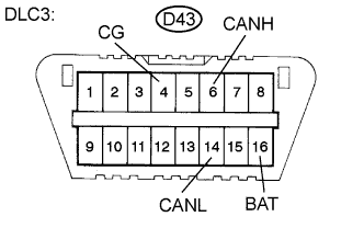
Measure the resistance according to the value(s) in the table below.
-
-
SKID CONTROL ECU WITH ACTUATOR
-
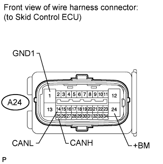
Disconnect the connector from the skid control ECU.
-
Measure the resistance according to the value(s) in the table below.
-
-
STEERING ANGLE SENSOR
-
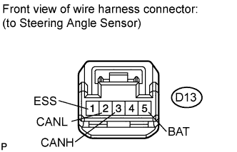
Disconnect the connector from the steering angle sensor.
-
Measure the resistance according to the value(s) in the table below.
-
-
YAW RATE SENSOR
-
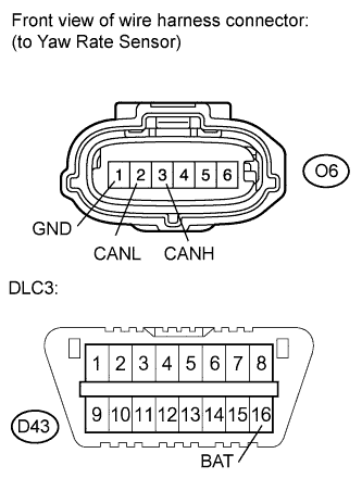
Disconnect the connector from the yaw rate sensor.
-
Measure the resistance according to the value(s) in the table below.
-
-
CENTER AIRBAG SENSOR ASSEMBLY
-
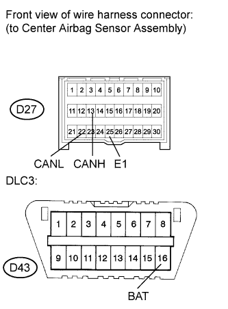
Disconnect the connector from the center airbag sensor assembly.
-
Measure the resistance according to the value(s) in the table below.
-
-
ECM
-
Disconnect the connector from the ECM.
-
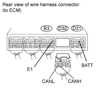
Measure the resistance according to the value(s) in the table below.
-
-
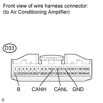
AIR CONDITIONING AMPLIFIER
-
Disconnect the connector from the air conditioning amplifier.
-
Measure the resistance according to the value(s) in the table below.
-
-
COMBINATION METER
-
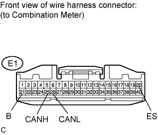
Disconnect the connector from the combination meter.
-
Measure the resistance according to the value(s) in the table below.
-
-
MAIN BODY ECU
-
Disconnect the connector from the main body ECU.
-
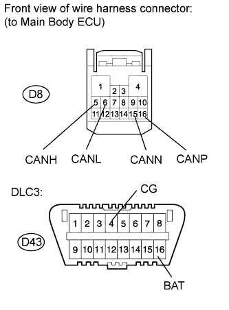
Measure the resistance according to the value(s) in the table below.
-
-
POWER STEERING ECU
-
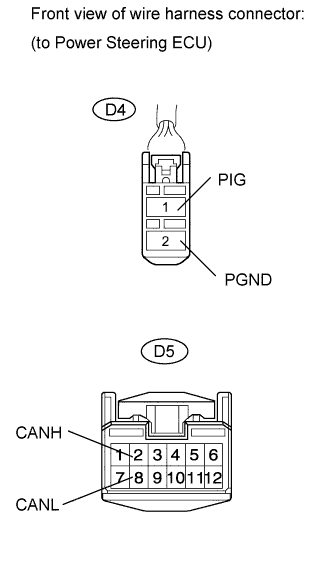
Disconnect the connectors from the power steering ECU.
-
Measure the resistance according to the value(s) in the table below.
-
-
CERTIFICATION ECU (w/ Smart Entry and Start System)
-
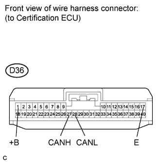
Disconnect the connector from the certification ECU.
-
Measure the resistance according to the value(s) in the table below.
-
-
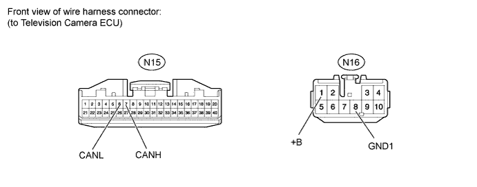
TELEVISION CAMERA ECU (w/ Parking Assist Monitor System)
-
Disconnect the television camera ECU connectors.
-
Measure the resistance according to the value(s) in the table below.
-
-
BACK DOOR ECU (w/ Power Back Door System)
-
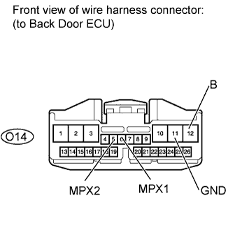
Disconnect the back door ECU connector.
-
Measure the resistance according to the value(s) in the table below.
-