| DTC Code | DTC Name |
|---|---|
| B2785 | Communication Malfunction between ECUs Connected by LIN |
DESCRIPTION
The certification ECU (smart key ECU assembly) monitors communication between all the ECUs connected to the certification ECU (smart key ECU assembly) system LIN bus lines. When the certification ECU (smart key ECU assembly) detects errors in communication with all the ECUs connected to the certification ECU (smart key ECU assembly) system LIN bus lines at a set interval and 3 times in a row, DTC B2785 will be output.
| DTC No. | DTC Detection Condition | Trouble Area |
|---|---|---|
| B2785 |
|
|
INSPECTION PROCEDURE
When using the intelligent tester with the ignition switch off to troubleshoot:
Connect the intelligent tester to the vehicle, and turn the courtesy switch on and off at 1.5-second intervals until communication between the tester and vehicle begins.
PROCEDURE
- Click here
CHECK HARNESS AND CONNECTOR (CERTIFICATION ECU - EACH ECU)
-
Disconnect the D36 connector.
-
Disconnect the 1E connector.
-
Disconnect the D28 connector.
-
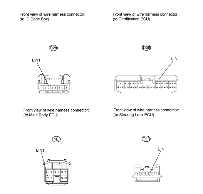
Disconnect the D10 connector.
-
Measure the resistance according to the value(s) in the table below.
Standard resistance Tester Connection Condition Specified Condition D36-10 (LIN) - D28-3 (LIN1) Always Below 1 Ω D36-10 (LIN) - 1E-7 (LIN1) Always Below 1 Ω D36-10 (LIN) - D10-5 (LIN) Always Below 1 Ω D36-10 (LIN) - Body ground Always 10 kΩ or higher -
Measure the voltage according to the value(s) in the table below.
Standard voltage Tester Connection Condition Specified Condition D36-10 (LIN) - Body ground Always Below 1 V
- OKClick here
- NGClick here
-
- Click here
CHECK FOR DTC
-
Connect the D36, D28 and D10 connectors.
-
Check for DTC.
Result Result Proceed to B2785 is output A B2785 is not output B
-
- Click here
CHECK FOR DTC
-
Connect the 1E connector.
-
Disconnect the D10 connector.
-
Check for DTC.
Result Result Proceed to B2785 is output A B2785 is not output B
-
- Click here
CHECK FOR DTC
-
Connect the D10 connector.
-
Disconnect the D28 connector.
-
Check for DTC.
Result Result Proceed to B2785 is output A B2785 is not output B
-
- Click here
REPLACE MAIN BODY ECU (INSTRUMENT PANEL JUNCTION BLOCK)
-
Replace the main body ECU with a normally-functioning or a new one.
- NEXTClick here
-
- Click here
CHECK FOR DTC
-
Recheck for DTC.
Result Result Proceed to B2785 is not output A B2785 is output B
-
- Click here
REPLACE STEERING LOCK ECU (STEERING LOCK ACTUATOR ASSEMBLY)
-
Replace the steering lock ECU (steering lock actuator assembly) with a new one (Click here).
- NEXTClick here
-
- Click here
CHECK FOR DTC
-
Recheck for DTC.
Result Result Proceed to B2785 is not output A B2785 is output B
-
- Click here
REPLACE ID CODE BOX (IMMOBILISER CODE ECU)
-
Replace the ID code box (immobiliser code ECU) with a new one.
- NEXTClick here
-
- Click here
CHECK FOR DTC
-
Recheck for DTC.
Result Result Proceed to B2785 is not output A B2785 is output B
-
- Click here
REPAIR OR REPLACE HARNESS OR CONNECTOR
- Click here
REPLACE CERTIFICATION ECU (SMART KEY ECU ASSEMBLY)
- Click here
END